Operating Instructions – MOVITRAC® B
17
3
Sizes 0XS / 0S / 0L
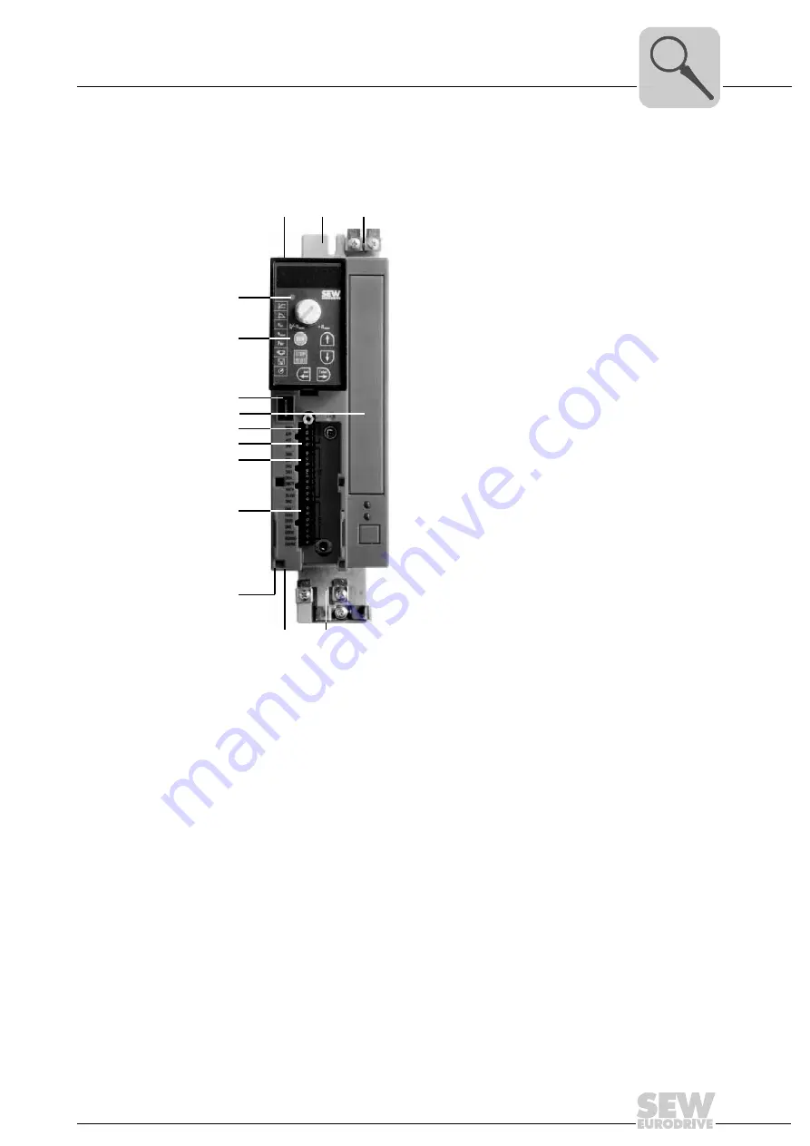
Unit structure
3.4
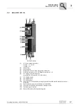
Sizes 0XS / 0S / 0L
9007199279301643
[1]
X1: Power supply connection:
3-phase: L1 / L2 / L3
1-phase: L / N
[2]
Fixing strap
[3]
PE connection
[4]
Shield plate for motor cable, fixing strap underneath
[5]
X2: Motor connection U / V / W / Brake connR / -R
[6]
X17: Safety contact for safe stop
(only MC07B...-S0: sizes 0S / 0L, 400 / 500 V)
[7]
X13: Digital outputs
[8]
X12: Digital inputs
[9]
X10: Analog input
[10]
Switch S11 for V mA switchover analog input (with size 0XS and 0S behind the removal
connector)
[11]
Option card slot (cannot be retrofitted / not for BG0XS)
[12]
Connection for optional communication / analog module
[13]
Optional keypad, inserted
[14]
Status LED (visible without optional keypad)
[3]
[4]
[5]
[12]
[1]
[7]
[8]
[10]
[9]
[11]
[13]
[14]
[6]
[2]
Summary of Contents for Movitrac B
Page 2: ...SEW EURODRIVE Driving the world...
Page 259: ......


