212
Operating Instructions – MOVITRAC® B
8
Technical data for accessories and options
Technical data
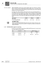
DC link connection
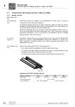
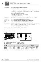
SEW-EURODRIVE recommends using the following cable sets for DC link connection.
These cable sets offer the appropriate dielectric strength and are color-coded. Color
coding is necessary because cross-polarity and ground faults could cause irreparable
damage to the connected equipment.
The length of the cables restricts the DC link connection to the permitted length of 5 m.
The cabless can be cut to length by the customer for connecting several units. The lugs
for connection to the regenerative power supply unit and an inverter are supplied with
the cable set. Use commercially available lugs for connecting additional inverters. The
inverters must then be connected to the regenerative power supply unit in star configu-
ration.
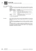
8.2.8
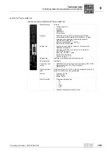
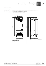
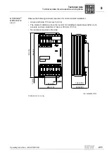
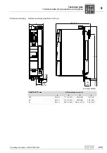
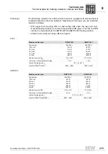
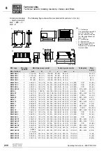
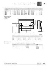
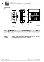
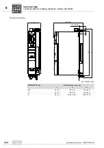
FHS11B/12B/13B support rail mounting
The FHS is used for support rail mounting of MOVITRAC
®
B frequency inverters and for
the submounting of braking resistors.
Cable set type
DCP12A
DCP13A
DCP15A
Part number
814 567 9
814 250 5
814 251 3
For connecting MOVITRAC
®
0055 ... 0110
0150 ... 0300
0400 ... 0750
INFORMATION
Refer to the "MOVIDRIVE
®
MDR60A Regenerative Power Supply Unit" system man-
ual for information on the DC link connection. This system manual can be ordered from
SEW-EURODRIVE.
Type
Part number
Size
Braking resistor
230 V
400/500 V
FHS11B
1820 724 3
0XS
BW4
BW2
FHS12B
1820 725 1
0S
BW027-003
BW072-003
FHS13B
1820 727 8
0L
P
i
f
kVA
Hz
n
Summary of Contents for Movitrac B
Page 2: ...SEW EURODRIVE Driving the world...
Page 259: ......

