216
Operating Instructions – MOVITRAC® B
8
Technical data for braking resistors, chokes and filters
Technical data
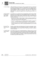
Wire resistors and
grid resistors
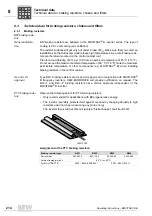
• Perforated sheet cover (IP20) open to mounting surface
• The short-term load capacity of the wire and grid resistors is higher than in the flat-
type braking resistors (
→
chapter "Braking resistor selection")
• A temperature switch is integrated in the BW..-T braking resistor
• A thermal over-current relay is integrated in the BW..-P braking resistor
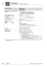
SEW-EURODRIVE recommends implementing additional protection against overload
for the wire and grid resistors by using a bimetallic relay with trip characteristics of trip
class 10 or 10A (in accordance with EN 60947-4-1). Set the trip current to the value I
F
(
→
following tables).
Do not use electronic or electromagnetic fuses because these can be triggered even in
case of short-term excess currents that are still within the tolerance range.
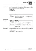
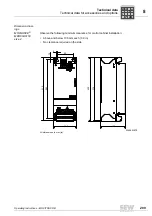
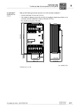
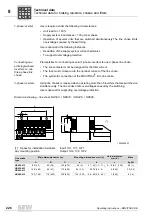
For BW..-T / BW..-P series braking resistors, you can connect the integrated tempera-
ture sensor or the over-current relay using a 2-core, shielded cable as an alternative to
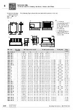
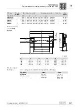
a bimetallic relay. The cable entry for BW..-T and BW..-P series braking resistors can be
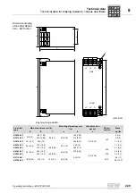
run from the front or the back (
→
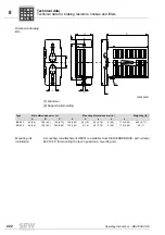
dimension drawing for BW... / BW..-T / BW..-P braking
resistors). Use filler plugs for tapped holes that are not connected.
The resistor surfaces will get very hot under a load of P
N
. Make sure that you select an
installation site that will accommodate these high temperatures. As a rule, braking resis-
tors are therefore mounted on the control cabinet roof.
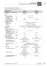
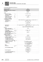
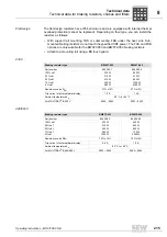
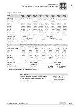
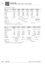
The performance data listed in the following tables indicate the load capacity of the brak-
ing resistors depending on their cyclic duration factor. The cyclic duration factor cdf of
the braking resistor is indicated in % and is based on a cycle duration of
≤
120 s.
P
i
f
kVA
Hz
n
Summary of Contents for Movitrac B
Page 2: ...SEW EURODRIVE Driving the world...
Page 259: ......

