Operating Instructions – MOVITRAC® B
29
4
Installation notes for basic unit – electrical aspects
Installation
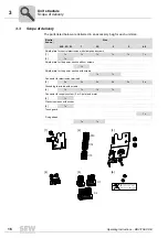
4.2.5
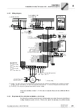
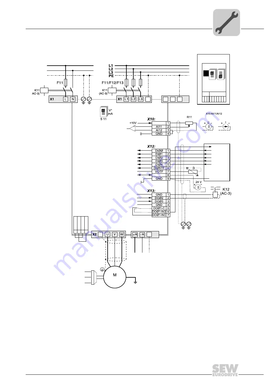
Wiring diagram
X4 is only available in sizes 1 – 5. From size 3 onwards, there are two additional PE ter-
minals.
4.2.6
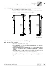
Requirements for cold plate installation – size 0 only
The frequency inverter power loss can be dissipated via coolers that work with different
cooling media (air, water, oil, etc.). This can be useful, for example, in restricted instal-
[1] In sizes 1, 2S, and 2, there is no PE connection next to the power supply connection terminals and motor connection terminals
[X1]/[X2]. Use the PE terminal next to the DC link connection [X4] (only size 1 – 5). For size 0, the plate is the PE connection.
[2] The MC07B..-S0 unit type must always be supplied with external voltage.
ON
OFF
ON
OFF
X45
X46
1 2 3 4 5 6
H L
⊥
FSC11B
MOVITRAC
®
B
S1
7
S2
X44
-> Section "Connecting braking resistors
BW.. / BW..-T / BW..-P"
PE
X2
X3
PE
X4
7
8
+U
Z
–U
Z
DGND
VO24
SOV24
SVI24
1
2
3
4
X17:
PE
PE
3 x AC 400/500 V / PE
3 x AC 230 V / PE
-> Section "Connecting
the brake rectifier"
X17 "Safe stop"
3 x 400 V:
5.5 – 75 kW, standard
3 x 400 V:
0.55 – 4.0 kW, MC07B..-S0
3 x 230 V:
3.7 – 30 kW, standard
3 x 230 V:
0.55 – 2.2 kW, MC07B..-S0
1 x AC 230 V / N / PE
[1]
[1]
[1]
L1
N
PE
Switchover
I signal -> U signal*
* = Factory setting
}
n13 = n11 + n12
REF1
24VIO
Enable/stop*
+24V input/output
(can be disabled with P808)
0 V – +10 V
0 (4) – 20 mA
Higher-level
controller
Digital
input
Digital
outputs
Reference f.
digital outputs
0 – 10 V*
0 – 20 mA; 4 – 20 mA
Ref. potential for analog signals
Error reset*
CW/stop
CCW/stop*
n11/n21*
n12/n22*
Supply voltage for TF/TH
Ref. potential for digital signals
Reference potential
Brake released*
Ready for operation*
Reference potential
Relay contact/fault*
Relay NO contact
Relay NC contact
[2]
PE
(
3-phase
Summary of Contents for Movitrac B
Page 2: ...SEW EURODRIVE Driving the world...
Page 259: ......


