32
Operating Instructions – MOVITRAC® B
4
Installation notes for basic unit – electrical aspects
Installation
4.2.10 Utilization category of contactors
• Use only contactors in utilization category AC-3 (EN 60947-4-1).
4.2.11 Required cross sections
• Supply system lead: Cross section according to rated input current I
line
at rated load
Motor lead: Cross section according to rated output current I
N
Electronics cables: Max. 1.5 mm
2
(AWG16) without conductor end sleeves
1)
Max. 1.0 mm
2
(AWG17) with conductor end sleeves
4.2.12 Cable lengths for individual drives
• The cable lengths depend on the PWM frequency. The permitted motor cable lengths
are listed in chapter "Project planning".
4.2.13 Unit output
• Only connect ohmic/inductive load (motor).
4.2.14 Switched inductances
• Use suppressors to suppress interference on
– Contactors
– Relays
– Solenoid valves
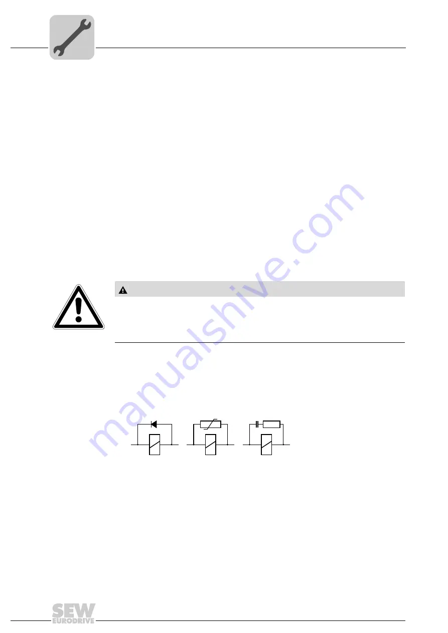
Suppressors are, for example, diodes, varistors, or RC elements:
Do not connect any suppressors directly to MOVITRAC
®
B. Connect suppressors as
closely as possible to the inductance.
4.2.15 PE supply system connection according to EN 61800-5-1
Leakage currents
≥
3.5 mA can occur during normal operation. Observe the following
for reliable PE connection:
• Supply system lead < 10 mm
2
:
– Route a second PE conductor with the same cross section as the supply system
lead in parallel to the protective earth via separate terminals, or
1) Never mount finely stranded cables without conductor end sleeves.
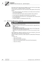
CAUTION
Switched inductances
Hazard: Malfunctions / damage to property.
• The minimum distance of switched inductances to the inverter must be at least
150 mm (5.91 in).
644450187
Summary of Contents for Movitrac B
Page 2: ...SEW EURODRIVE Driving the world...
Page 259: ......


