Operating Instructions – MOVITRAC® B
35
4
Installing accessories and options – electrical aspects
Installation
4.3.3
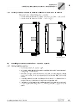
Flat-design resistors with FKB11B / FKB12B / FKB13B and FHS11B / FHS12B / FHS13B
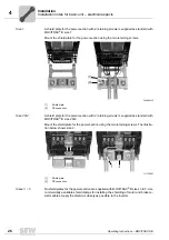
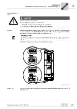
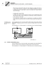
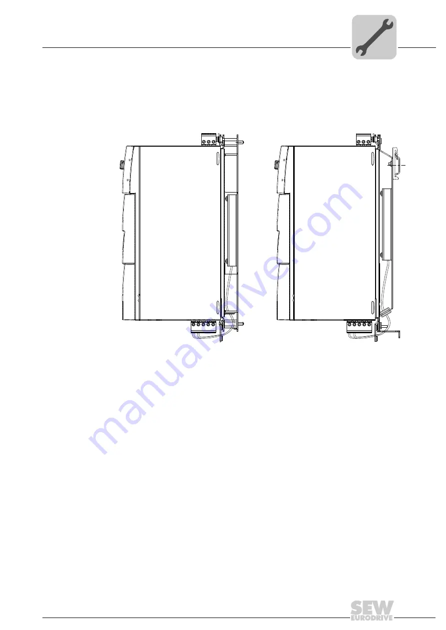
Proceed as follows to install flat-type braking resistors:
• FKB11B / FKB12B / FKB13B: Installation on the back panel of the control cabinet:
• FHS11B / FHS12B / FHS13B: Installation with mounting rail
4.4
Installing accessories and options – electrical aspects
4.4.1
Braking resistor connection
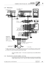
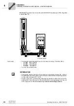
• Shorten the cables to the required length.
• Use 2 tightly twisted leads or a 2-core shielded power cable. Cable cross section ac-
cording to trip current I
F
of F16.
• Protect the braking resistor with a bimetallic relay (F16, see wiring diagram) with trip
class 10 or 10A. Set the trip current according to the technical data of the braking
resistor.
• For braking resistors in the BW..-T series, you can connect the integrated thermostat
using a 2-core, shielded cable as an alternative to a bimetallic relay.
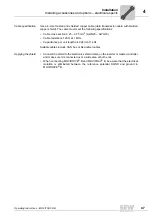
• The flat-type braking resistors have internal thermal overload protection (fuse cannot
be replaced). Install the flat-type braking resistors together with the appropriate touch
guard.
18014399298721547
FKB11B
FKB12B
FKB13B
FHS11B
FHS12B
FHS13B
Summary of Contents for Movitrac B
Page 2: ...SEW EURODRIVE Driving the world...
Page 259: ......


