36
Operating Instructions – MOVITRAC® B
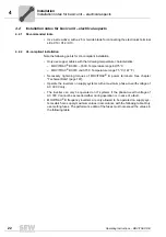
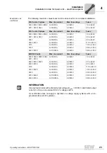
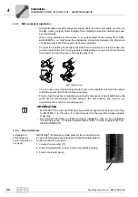
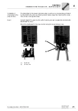
4
Installing accessories and options – electrical aspects
Installation
4.4.2
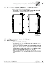
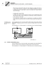
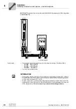
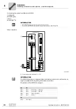
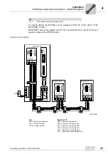
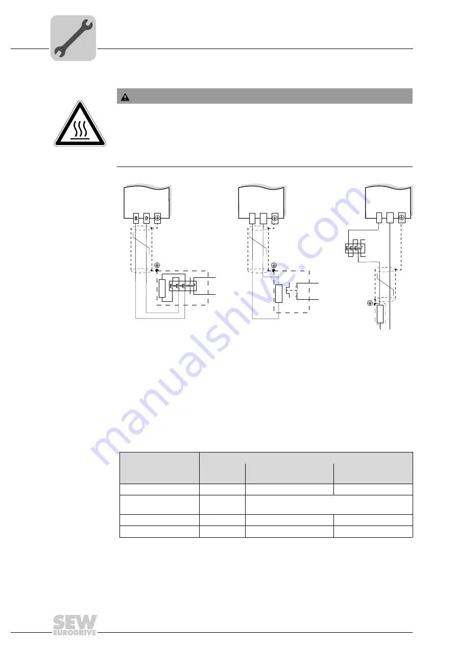
Connecting braking resistor BW..-P / BW..-T / BW.. to X3 / X2
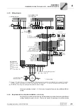
Set a terminal to "/Controller inhibit". K11 must be opened and "/Controller inhibit" must
receive a "0" signal in the following cases:
• BW..-P: The auxiliary contact trips
• BW..-T: The internal temperature switch trips
• BW..: The external bimetallic relay F16 trips
The resistor circuit must not be interrupted.
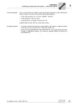
Overload protection for braking resistors BW:
WARNING
The surfaces of the braking resistors get very hot when the braking resistors are loaded
with P
N
.
Risk of burns and fire.
• Choose a suitable installation location. Braking resistors are usually mounted on top
of the control cabinet.
• Do not touch the braking resistors.
9007199281070731
T2
T
1
BW..-T
RB2
RB1
X2/X3:
+R -R PE
8
9
BW..
F16
X2/X3:
+R -R PE
8
9
4
6
X2/X3:
+R -R PE
BW..-P
→
K11
97
95
98
96
F16
→
K11
→
K11
Overload protection
Braking resistor type
Design
specified
Internal temperature
switch (..T / ..P)
External bimetallic
relay (F16)
BW..
–
–
Required
BW..-T
1)
/ BW..-P
1) Permitted installation: On horizontal or vertical surfaces with brackets at the bottom and perforated sheets
at top and bottom.
Improper installation:
On vertical surfaces with brackets at the top, right or left.
–
One of the two options (internal temperature
switch/external bimetallic relay) is required.
BW..-003 / BW..-005
Adequate
–
Permitted
BW1 – BW4
Adequate
–
–
Summary of Contents for Movitrac B
Page 2: ...SEW EURODRIVE Driving the world...
Page 259: ......

