Operating Instructions – MOVITRAC® B
37
4
Installing accessories and options – electrical aspects
Installation
4.4.3
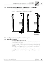
Braking resistor installation
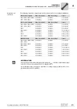
• The supply cables to the braking resistors carry a high voltage (approx. DC 900 V)
during rated operation.
• The surfaces of the braking resistors get very hot when the braking resistors are
loaded with P
N
. Choose a suitable installation location. Braking resistors are usually
mounted on the control cabinet roof.
4.4.4
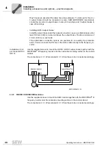
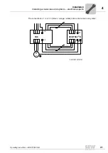
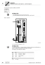
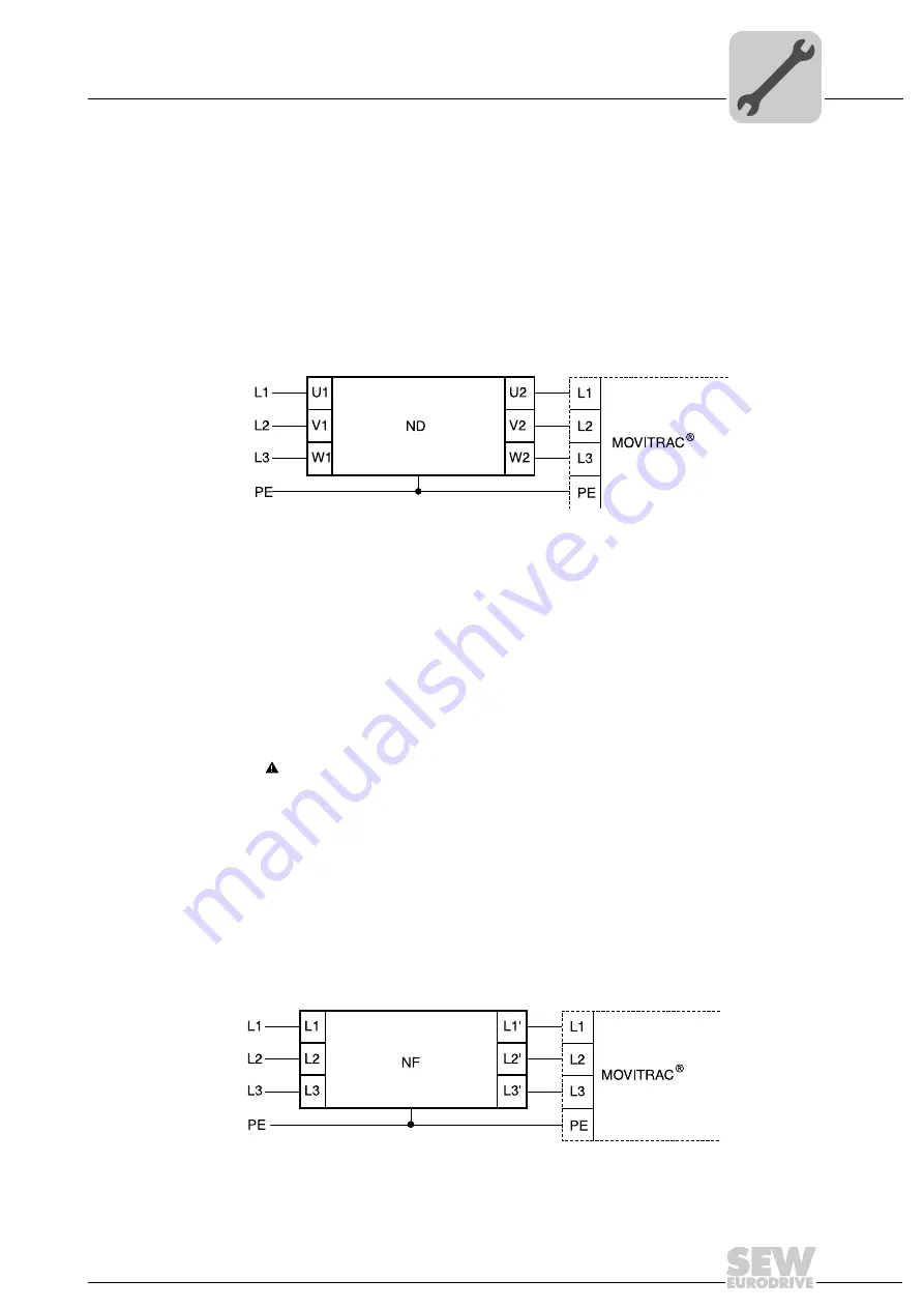
ND line choke
Connecting ND series line choke
Installing optional
power components
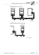
Input contactor for several units
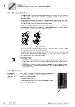
Connect a line choke for limiting the inrush current:
• For 5 or more 3-phase units
• For 2 or more 1-phase units
4.4.5
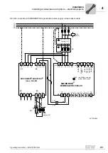
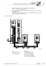
NF line filters
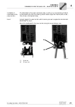
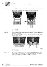
• Using the NF line filter, you can maintain limit value class C1/B with MOVITRAC
®
B
sizes 0 to 5.
•
NOTICE
Possible damage to property
Damage to the input level.
– No switching is permitted between the line filter and MOVITRAC
®
B.
• Install the line filter close to the inverter but outside the minimum clearance for cool-
ing.
• Restrict the cable between the line filter and the inverter to the absolute minimum
length required, and never more than 400 mm (15.7 in). Unshielded, twisted cables
are sufficient.
• Use unshielded cables for the supply system connection as well.
Connecting NF line filters
9007199272823563
B
18014398527568907
B
Summary of Contents for Movitrac B
Page 2: ...SEW EURODRIVE Driving the world...
Page 259: ......

