40
Operating Instructions – MOVITRAC® B
4
Installing accessories and options – electrical aspects
Installation
Only 5 loops are possible if the cable has a large diameter. To make up for this, 2 or
3 output chokes should be connected in series. SEW-EURODRIVE recommends
connecting in series 2 output chokes in case of 4 windings, and 3 output chokes in
case of 3 windings.
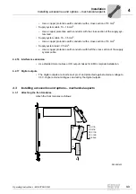
• Installing HD012 output chokes:
Install the output choke under the respective inverter. Leave a ventilation space of at
least 100 mm (3.94 in) below and above the output choke. Provide a clearance of
10 mm (0.39 in) on each side.
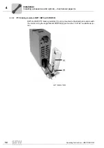
Three alternative connection options are provided for connecting the protective
earth. You can connect the PE line of the motor cable directly to the frequency in-
verter.
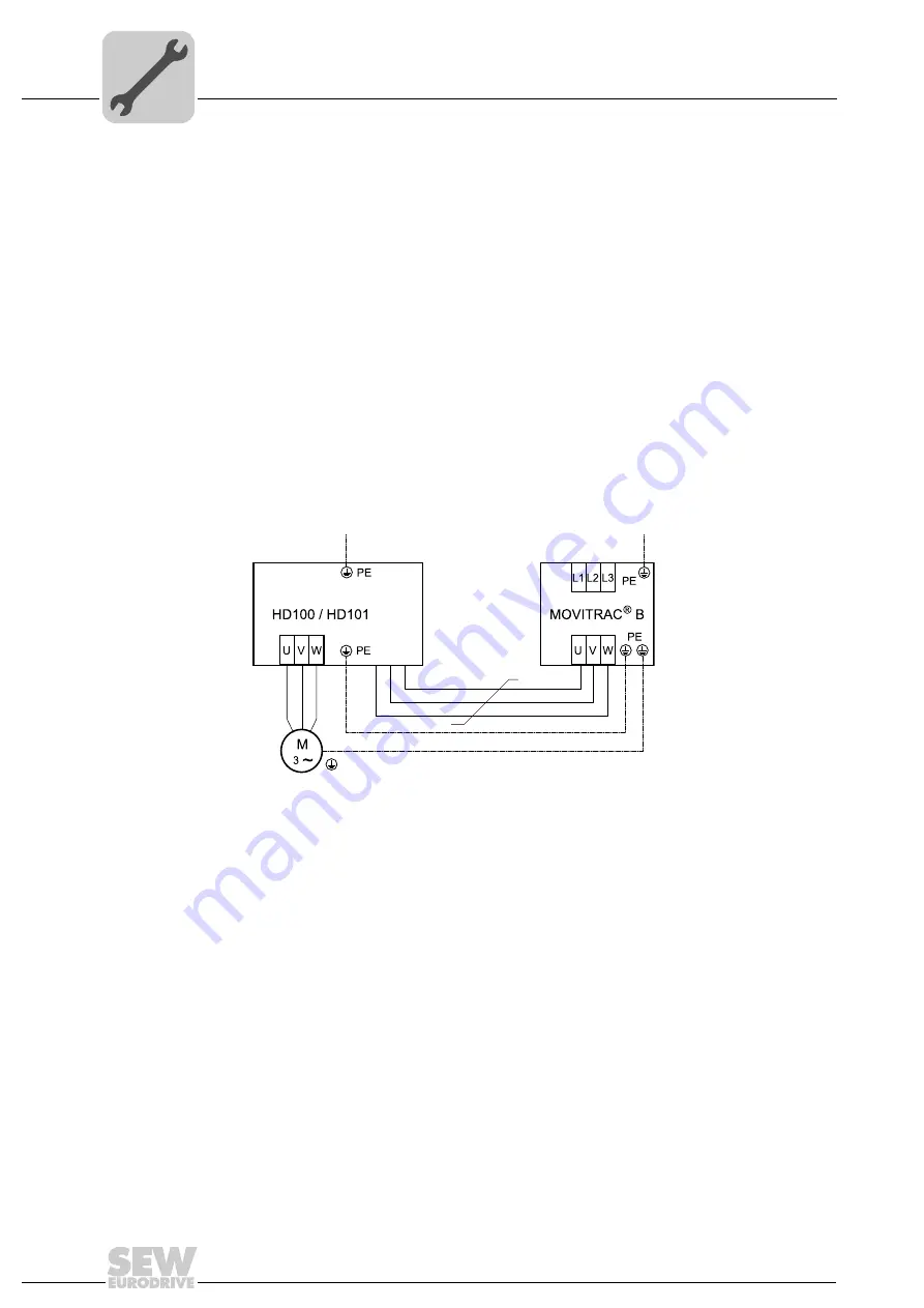
Installation of out-
put choke HD100 /
HD101
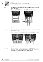
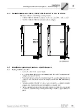
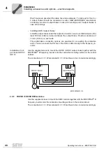
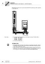
Use the supplied screws to mount the HD100 / HD101 output choke together with the
MOVITRAC
®
B frequency inverter onto the conductive mounting surface in the control
cabinet.
The connections U / V / W are labeled U / V / W and have to be connected accordingly.
4.4.9
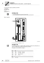
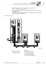
FKE12B / FKE13B EMC-modules
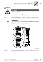
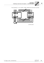
Use the supplied screws to mount the EMC module together with the MOVITRAC
®
B
frequency inverter onto the conductive mounting surface in the control cabinet.
The connections U / V / W are labeled U / V / W and have to be connected accordingly.
9007200304810123
Summary of Contents for Movitrac B
Page 2: ...SEW EURODRIVE Driving the world...
Page 259: ......

