Operating Instructions – MOVITRAC® B
49
4
Installing accessories and options – electrical aspects
Installation
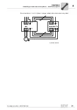
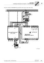
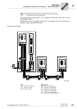
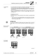
To simplify cabling, the DFP21B can be supplied with DC 24 V from X46.7 of the
MOVITRAC
®
to X26.7.
MOVITRAC
®
B must be supplied with DC 24 V at terminals X12.8 and X12.9 when it
supplies voltage to the DFP21B option.
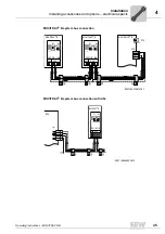
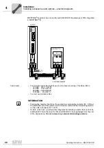
System bus connection
X12:9
GND reference potential for digital inputs
X12
6140140043
X45 X46
1 2 3 4 5 6
H L
^
FSC11B
MOVITRAC
®
B
S1
OFF
ON
7
S2
X44
X45 X46
1 2 3 4 5 6
H L
^
FSC11B
MOVITRAC
®
B
S1
OFF
ON
7
S2
X44
X45 X46
1 2 3 4 5 6
H L
^
FSC11B
MOVITRAC
®
B
S1
OFF
ON
7
S2
X44
X26
1 2 3 4 5 6 7
X24
H1
H2
DFP21B
0 1
2
2
2
2
0
1
2
3
2
2
2
AS
4
5
6
X30
ADDRESS
1
6
5
9
X12
1
2
3
4
5
6
7
8
24V IO
24V
-
+
9
GND
=
RUN
BUS
FAULT
DFP
GND = System bus reference
SC11 = System bus high
SC12 = System bus low
MOVITRAC
®
B
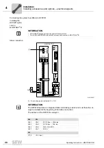
GND = System bus reference
SC22 = System bus outgoing low
SC21 = System bus outgoing high
SC12 = System bus incoming low
SC11 = System bus incoming high
S12 = System bus terminating resistor
Summary of Contents for Movitrac B
Page 2: ...SEW EURODRIVE Driving the world...
Page 259: ......

