86
Operating Instructions – MOVITRAC® B
5
Communication and unit profile
Startup
Setting: RS485,
FIELDBUS, SBus
With this setting, the control word defined in the process output data channel is updated
by the set control signal source (RS485 / FIELDBUS / system bus).
The digital inputs and the IPOS
plus®
control program continue to be involved in the con-
trol process.
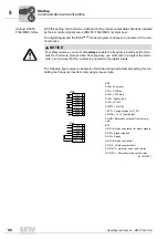
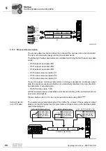
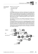
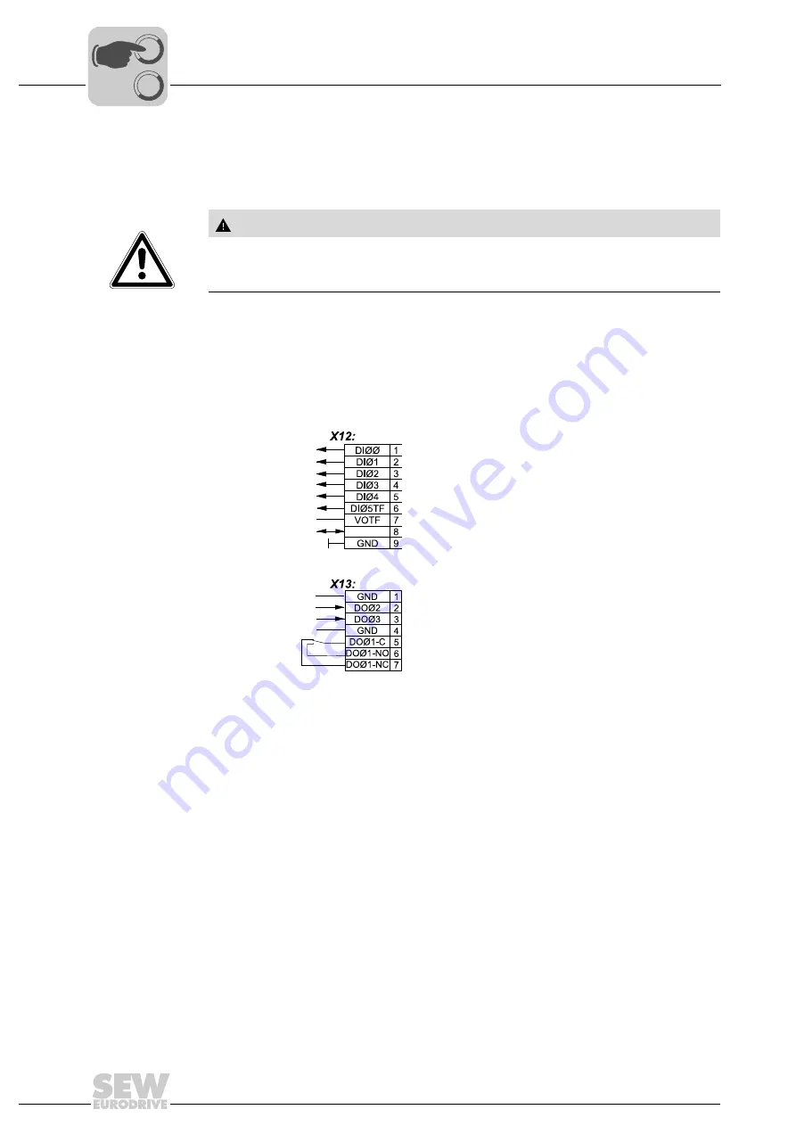
The following figure gives an example of terminal wiring and parameter setting for con-
trolling the frequency inverter solely using process data.
NOTICE
For safety reasons, you must also
always
enable the frequency inverter at the termi-
nals for control via process data. Consequently, you must wire or program the termi-
nals in such a way that the inverter is enabled via the digital inputs.
X12
DI00 = Fault reset
DI01 = CW/Stop
DI02 = CCW/Stop
DI03 = Enable/Stop
DI04 = n11/n21
DI05TF = n12/n22
VOTF = Supply voltage for TF/TH
24VIO4 = + 24 V input/output
DGND = Reference potential for binary sig-
nals
X13
GND = Reference potential for binary signals
DO02 = Brake released
DO03 = Ready
GND = Reference potential
DO01-C = Relay contact/fault
DO01-NO = Normally open contact relay
DO01-NC = Normally closed contact relay
8674167947
24VIO
00
I
Summary of Contents for Movitrac B
Page 2: ...SEW EURODRIVE Driving the world...
Page 259: ......


