98
Operating Instructions – MOVITRAC® B
5
Communication and unit profile
Startup
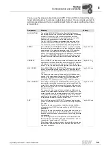
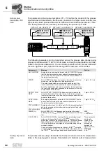
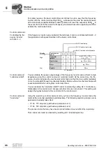
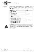
Control word 1
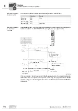
Control word 1 includes the most important drive functions of the basic control block as
well as the function bits for setpoint functions that are generated in the MOVITRAC
®
B
frequency inverter in the higher-order byte.
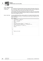
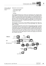
These internal setpoint functions are activated by setting parameter P100 to fixed set-
point or motor potentiometer and setting the matching bits in control word 1. Any speed
setpoint entered via an SBus process output data word will no longer be effective.
Motor potentiome-
ter via fieldbus
The setpoint function motor potentiometer is controlled via the fieldbus interface in the
same way as with the standard input terminals. The process ramp that may be entered
via an additional process output data word has no effect on the motor potentiometer
function. Only the following motor potentiometer integrators will be used:
• P150 T3 ramp up
• P151 T4 ramp down
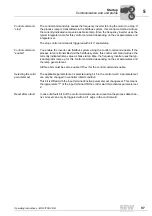
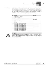
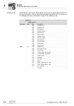
Bit
Function
Assignment
0
Fixed definition
Controller inhibit "1" / enable "0"
1
Enable "1" / rapid stop "0"
2
Enable "1" / stop "0"
3
Reserved
4
Integrator switchover
5
Parameter set switchover
6
Reset
7
Reserved
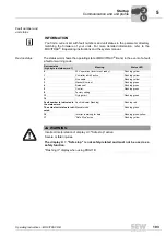
8
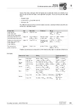
Direction of rotation
for motor potentiome-
ter
0 = CW direction of rotation
1 = CCW direction of rotation
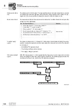
9
10
Motor potentiometer
acceleration
Motor potentiometer
deceleration
10 9
0 0 = no change
1 0 = down
0 1 = up
1 1 = no change
11
12
Selection of the inter-
nal fixed setpoints
n11 - n13 or n21 -
n23
12 11
0 0 = Speed setpoint via process output data word 2
0 1 = Internal setpoint n11 (n21)
1 0 = Internal setpoint n12 (n22)
1 1 = Internal setpoint n13 (n23)
13
Fixed setpoint swi-
tchover
0 = Fixed setpoints of the active parameter set can be selected using bit
11/12
1 = Fixed setpoints of the other parameter set can be set using bit 11/12
14
Reserved
Set reserved bits to zero.
15
Reserved
Set reserved bits to zero.
00
I
Summary of Contents for Movitrac B
Page 2: ...SEW EURODRIVE Driving the world...
Page 259: ......

