Operating Instructions – MOVITRAC® B
99
5
Communication and unit profile
Startup
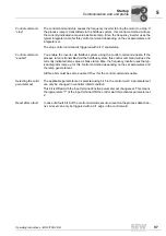
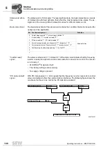
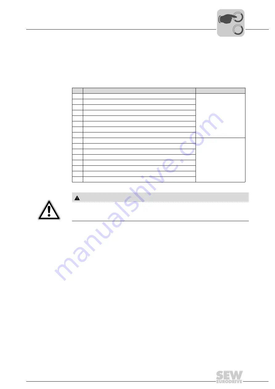
Control word 2
Control word 2 contains the function bits for the most important drive functions in the
basic control block; the virtual input terminals in the higher-order part. These are freely-
programmable input terminals that are not physically available due to missing hardware
(option cards). In this way, the input terminals are represented on the virtual input termi-
nals of the fieldbus. Each virtual terminal is assigned to an optional and
physically un-
available
input terminal. Its functionality can be programmed as required.
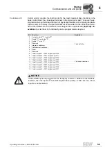
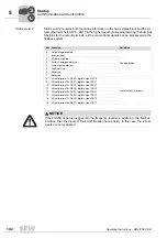
Bit Function
Definition
0
Controller inhibit "1" / enable "0"
Fixed definition
1
Enable "1" / rapid stop "0"
2
Enable "1" / stop "0"
3
Reserved
4
Integrator switchover
5
Parameter set switchover
6
Reset
7
Reserved
8
Virtual terminal 1 = P610 / digital input DI10
Virtual input terminals
9
Virtual terminal 2 = P611 / digital input DI11
10 Virtual terminal 3 = P612 / digital input DI12
11
Virtual terminal 4 = P613 / digital input DI13
12 Virtual terminal 5 = P614 / digital input DI14
13 Virtual terminal 6 = P615 / digital input DI15
14 Virtual terminal 7 = P616 / digital input DI16
15 Virtual terminal 8 = P617 / digital input DI17
NOTICE
If the FIO21B option is plugged into the frequency inverter in addition to the fieldbus
interface, then the inputs of the FIO21B option have priority. In this case, the virtual
inputs are not evaluated.
00
I
Summary of Contents for Movitrac B
Page 2: ...SEW EURODRIVE Driving the world...
Page 259: ......

