background image


2 AQUAPHON system │ 

5


What is to be located?
The purpose determines the choice of 

application

.


Where is it to be located?
Conditions on the ground determine the choice of 

contact 

point

.

2.1.3.1  Switch-on mode

The receiver always automatically determines the switch-on 

mode. There are two options:


Startup with user guide


Direct startup

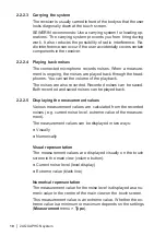
The situation when the receiver is switched on determines which 

switch-on mode is used. The receiver checks whether or not cer-

tain steps have already been performed. These steps include:


System components have been connected (e.g. carrying rod 

and a ground microphone).


System components have already been switched on before 

the receiver.

For more detailed information about switching on dependent on 

switch-on mode, please refer to section 3.2 on page 21.

Startup with user guide

Target 

group:

Users with little experience of using the system.


– The user is unsure of which system components 

to select for a certain application and the corre-

sponding contact point.

The user first switches on the receiver. Once an application and 

the contact point have been selected, the receiver provides de-

tailed instructions about which components are to be connected 

and switched on in what order.

Direct startup

Target 

group:

Experienced users.


– The user knows which components of the sys-

tem to select for a certain application and the 

corresponding contact point.

Summary of Contents for AQUAPHON A 200

Page 1: ...16 09 2019 a 107378 en AQUAPHON A 200 receiver Operating Instructions...

Page 2: ...A 200 receiver Connectors Fig 1 Front Fig 2 View from above LED Light sensor Touch screen Connectors Charging socket USB port Microphone socket ON OFF key Activation keys...

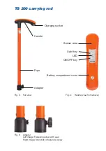
Page 3: ...socket Fig 3 Full view Sensor area Fig 4 Handle view from above Fig 5 Adapter Left image Fastening screw with seal Right image Star knob in fastening screw Handle Pipe Adapter Light key LED ON OFF ke...

Page 4: ...or death A CAUTION Risk of personal injury Could result in injury or pose a risk to health NOTICE Risk of damage to property Note Tips and important information Numbered lists numbers letters are use...

Page 5: ...2 2 3 Carrying the system 10 2 2 2 4 Playing back noises 10 2 2 2 5 Displaying the measurement values 10 2 2 2 6 Automatic power off 11 2 2 2 7 Main view 11 2 2 3 TS 200 carrying rod 15 2 2 4 Microph...

Page 6: ...e display 33 3 6 6 Resetting filter settings 33 3 7 Playing back noise repeatedly 34 3 7 1 Opening the Audio Player menu 34 3 7 2 Playing back noise 36 3 7 2 1 Playing back noise with recorded filter...

Page 7: ...batteries individually using the AC DC adapter or vehicle cable 58 5 2 Handling faulty lithium ion rechargeable batteries 59 5 2 1 Identifying faulty batteries 59 5 2 2 Removing the batteries from the...

Page 8: ...icrophones for the applications 74 6 5 Operating the system by activation key or sensor area 75 6 6 Accessories 76 6 7 Declaration of conformity 76 6 8 Note about the firmware open source software 77...

Page 9: ...y be used when performing repairs Changes or modifications to this product may only be carried out with the approval of Hermann Sewerin GmbH Use only Hermann Sewerin GmbH accessories for the product H...

Page 10: ...instructions apply to the A 200 receiver with firmware version 2 x and higher The manufacturer reserves the right to make changes 1 3 Intended use The AQUAPHON system is intended for professional ind...

Page 11: ...afety information without fail Risk of personal injury health risk Handle the components carefully and safely both during trans port and when working Proceed with extreme caution in the vicinity of el...

Page 12: ...hone slips off the contact point The hearing protection function activates when the individu al hearing protection threshold setting is exceeded When the noise from the source of interference ceases h...

Page 13: ...icrophone System components have already been switched on before the receiver For more detailed information about switching on dependent on switch on mode please refer to section 3 2 on page 21 Startu...

Page 14: ...be used for Leak detection Pipe location 2 1 3 3 Contact points Each application allows the system to be used on certain contact points The contact point is the area on which a microphone is placed Th...

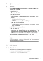
Page 15: ...are required for the touch microphone UM 200 universal microphone AC 200 SK4 case The system can be transported and stored in the case The batteries for the components A 200 TS 200 and F8 can be si mu...

Page 16: ...n Certain areas of the touch screen are touch sensitive Actions are performed by touching these areas buttons All of the buttons have a thick dark grey outline Only your finger or a touch pen should b...

Page 17: ...receiver has two activation keys Only one of the two keys needs to be pressed to measure LED The LED indicates the operating status Information about what the LED signals mean can be found in section...

Page 18: ...ack The noises are also recorded Recorded noises can be saved Both recorded and saved noises can be played back 2 2 2 5 Displaying the measurement values Various measurement values are calculated from...

Page 19: ...in when you want to continue work Switch off backlight The receiver backlight switches off if it is not operated for a specified period of time The receiver remains switched on If and when the automat...

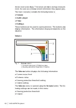
Page 20: ...us The buttons also display information The information displayed depends on the situation Volume Fig 7 Volume button 1 Current noise level 2 Extreme value 3 Hearing protection threshold 4 Volume The...

Page 21: ...Fig 8 Audio player button The Audio player menu is opened using the Audio player but ton The following actions can be performed in this menu Play back delete save noise Load and play back noise from...

Page 22: ...Filter limits limit frequencies of the bandpass Scale for the frequency axis Settings The Settings button displays the following information Application or connected microphone Set type of extreme va...

Page 23: ...carefully and safely both during trans port and when working Be particularly careful when the touch microphone and probe tip are screwed onto the carrying rod Do not lean on the carrying rod Star kno...

Page 24: ...Light key The light key on the carrying rod is used to switch the light source for the TM 200 touch microphone on and off Note The light source of the UM 200 universal microphone is switched on and o...

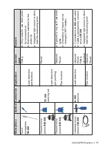
Page 25: ...umi nate the measuring point Ground micro phone BM 200 Leak detection pin pointing Pipe location Paved Ground micro phone BM 230 Unpaved Paved If ground is very soft use extra spike Orientation of tri...

Page 26: ...owerful LEDs Do not look directly into the light Never shine the light into the eyes of another person Contact adapter The contact adapter is an accessory with which the microphone can be attached dir...

Page 27: ...on determines the so called switch on mode If you want the system to start in a specific switch on mode you have to switch on the components in a certain order When the system is switched on a radio c...

Page 28: ...ion 5 1 on page 57 NOTICE Risk of damage when changing lithium ion bat teries The battery compartments of the components contain parts that could get damaged when the batteries are being replaced Only...

Page 29: ...ing Microphones can be rinsed under running water Dry the entire microphone connector if necessary Never unscrew the fastening screw all the way out of the thread to minimise the risk of getting dirt...

Page 30: ...de Starting with the user guide works from the following starting point All components are switched off A microphone has not yet been selected or connected 1 Switch the A 200 receiver on A start scree...

Page 31: ...hing menu Application leak detection contact point Fitting 4 Follow the instructions in the specified order As soon as a step is complete the corresponding symbols appear in colour Blue The specified...

Page 32: ...to TS 200 carry ing rod Universal microphone UM 200 to receiver A 200 All components are switched off 1 Switch on carrying rod TS 200 Note Do not touch the sensor area of the carrying rod when switchi...

Page 33: ...ich microphone can be found in section 6 4 on page 74 The easiest way to tell whether or not a measurement is being taken is by looking at the main view A measurement value is displayed during a measu...

Page 34: ...protection threshold Protective effect Display colour 1 very high low red 2 high medium orange 3 medium high yellow 4 low very high green A CAUTION Health hazard If the hearing protection threshold is...

Page 35: ...s the frequencies of the noise This frequen cy analysis is displayed in a graph Fig 15 Frequency graph 1 Frequency axis 2 Lower stopband 3 Lower filter limit 4 Graph of frequency analysis 5 Passband 6...

Page 36: ...on after switching on the system 3 6 1 3 Purpose of adjustment The filter limits should be set in such a way that any leak noise is accentuated above other noises e g sound interference and is thus cl...

Page 37: ...bol for the application Fig 16 Settings button in the main view Left image View for default settings shows the application Right image View for adjusted filter settings shows the microphone 3 6 2 Open...

Page 38: ...Confirm The filter settings will now be applied The re ceiver will switch back to the main view The receiver works with the current filter settings until they are next adjusted 3 6 3 Scanning The scan...

Page 39: ...nually adjusting filters There are two ways of manually adjusting the filter limits Quick adjustment Exact adjustment 3 6 4 1 Adjusting filter limits quickly A quick adjustment involves resetting both...

Page 40: ...changes its appearance The filter limit stop range that can be adjusted is displayed in orange 2 Reset the selected filter limit Tap on one of the Move buttons until the desired position is reached 3...

Page 41: ...he filter limits Scaling is only possible if the upper filter limit is set at or below half of the frequency range Frequency range scaling levels Display scalable if upper filter limit 0 12 kHz 6 kHz...

Page 42: ...nctions only become available when at least one measurement has been recorded Alternatively you can also load a measurement from the memory The main view is open Tap the Audio player button The Audio...

Page 43: ...value selection represents measurements by their measurement value numeric value and bar The measurement value selection is divided into the following two areas 7 connected segments for up to 7 record...

Page 44: ...You can play back a noise in the following ways With recorded filter limits With current filter limits Faster than recorded Note You cannot adjust the volume during playback of a recorded noise 3 7 2...

Page 45: ...r settings button again The dot on the Filter settings button turns grey again 3 7 2 3 Playing back noise faster If a noise contains a lot of low frequencies it is often hard to hear Audibility usuall...

Page 46: ...e receiver is switched off SEWERIN recommends Save measurements that contain a lot of information In this way you can create a database to com pare noises The Audio player 1 2 menu is open 1 Tap the m...

Page 47: ...rmation about this measurement Save the recorded noise again and in doing so add the rele vant additional information Previous additional information is overwritten 3 9 Deleting the recorded measureme...

Page 48: ...lected The segment is inverted 2 Tap the Open button The Load noise menu appears Fig 23 Load noise menu Top left Filter by date button Centre List of saved measurements 3 Tap the relevant measurement...

Page 49: ...values that have been saved for the data can be se lected as filter criteria Example Measurements were saved in 2017 and 2019 No measure ments were saved in 2018 The filter criteria available for sele...

Page 50: ...ppears 3 Tap the Clear button Delete mode is enabled The dot on the Clear button turns red The measurements in the list appear in red 4 Tap the measurement you want to delete in the list The meas urem...

Page 51: ...the relevant measurement in the measurement value selection 2 Tap Scroll The Audio player 2 2 view appears The availa ble information about the selected measurement is displayed The following informat...

Page 52: ...asurement the measurement is terminated and not saved Locking 1 Briefly press the ON OFF key The receiver switches to the Switching off menu for 3 seconds 2 Tap Lock display The display switches off i...

Page 53: ...ly affect the receiver 4 2 Setting actions The settings in the Measurement and Device menus are imple mented as follows Select Enable disable Set value Fig 25 Menu sample diagram Very top Menu item wi...

Page 54: ...ng is applied immediately without further confirma tion The receiver goes back up a menu level The selected setting is displayed in the higher menu level 4 2 2 Enabling disabling Fig 27 Enabling disab...

Page 55: ...he value The down key decreases the value 2 Apply the settings by pressing Confirm The receiver goes back up a menu level 4 3 Settings in the Measurement menu Note The settings in the Measurement menu...

Page 56: ...enu appears 5 Tap Back again to return to the main view 4 3 1 Method The average noise level is displayed There are two ways of cal culating the average noise level The difference between the two meth...

Page 57: ...activates when the set hearing protection threshold is exceeded Hearing protection can work in two ways The options are Muted The noise is muted so that it can just about be heard above the hearing pr...

Page 58: ...sor area with your thumb to start the measurement Pressing the sensor area again ends the measurement 4 3 5 Timer A timer can be displayed on the touch screen The timer shows how long a measurement ha...

Page 59: ...enu This allows you to change the application when the receiver is switched on Typically you might want to change application in the following locating situations When changing from prelocation to pin...

Page 60: ...ons in the specified order Once all the specified components have been connected the receiver automatically switches to the main view 4 5 Settings in the Device menu Note The settings in the Device me...

Page 61: ...YYYY Time format 12 h 24 h Language English Service Information Calibration Fig 30 Device menu 3 Adjust the settings as required The Device menu is divided into the four views General Time Date Regio...

Page 62: ...klight can switch off automatically if it is not operated for a specified period of time The receiver remains switched on Note This function helps save energy It means that the receiver can be used fo...

Page 63: ...n is disabled a per manent value can be set for the brightness of the touch screen 4 5 5 Time The receiver features an internal clock The set time is displayed in the main view on the Settings button...

Page 64: ...n the user interface can be displayed in various lan guages There is a range of languages to choose from 4 5 10 Information The relevant current technical information is stored in each re ceiver The f...

Page 65: ...temperature falls below or exceeds the limit values charging stops until the temperature returns to within the per mitted range There are two ways of charging the components All components at the same...

Page 66: ...Charging starts automatically After less than 7 5 hours the charging process is complete 5 1 2 Charging batteries individually using the AC DC adapter or vehicle cable The components are connected di...

Page 67: ...g the housing the components can be damaged mechanically or by electrostatic discharge Lithium ion batteries must only be removed if there is reason able suspicion that they might be faulty Only SEWER...

Page 68: ...ion 5 2 1 before removing the batteries Avoid electrostatic discharges at all costs e g by using an ESD workstation Fig 32 Back of the A 200 receiver White circles Screws of the battery compartment co...

Page 69: ...over 3 Disconnect the electrical supply to the faulty battery by pulling off the white plug Never sever the cable 4 Remove the battery 5 Screw the battery compartment cover back on 5 2 3 Removing the...

Page 70: ...ent is sealed with the battery compartment cover The carrying rod must be switched off 1 Undo the three screws securing the battery compartment cov er on the underside of the handle 2 Remove the batte...

Page 71: ...be used Never switch the receiver off during the calibration process Always use a touch pen for calibration Work with extreme care The main view is open 1 Tap the Settings button The Settings menu app...

Page 72: ...WERIN recommends Always remove significant contamina tion immediately Please note the following special points Carrying rod Never use compressed air or a water jet for cleaning Microphones Microphones...

Page 73: ...102 IC 7994A EZ1300102 Features Display 5 7 TFT display 640 x 480 pixels VGA LED backlight Interface micro USB Memory 90 MB internal Processor RISC 32 bit DSP Operation Touch screen ON OFF key two act...

Page 74: ...Hz Increment minimum 50 Hz Sampling rate 16 bit 24 kHz Data transmission Transmission frequency 2 408 2 476 GHz 38 channels Radio range 2 m Transmission bandwidth 0 12 kHz Communication SDR Sewerin D...

Page 75: ...without microphone IP67 with microphone Non permitted operating environments in potentially explosive areas Power supply Power supply lithium ion battery rechargeable 1357 0003 Operating time typical...

Page 76: ...Operating conditions Operating temperature 20 60 C Storage temperature 25 70 C Protection rating IP65 without TS 200 carrying rod IP67 with TS 200 carrying rod Non permitted operating environments in...

Page 77: ...each 15 cd Operating conditions Operating temperature 20 80 C Storage temperature 25 80 C Protection rating IP68 Non permitted operating environments in aggressive media in potentially explosive areas...

Page 78: ...d etc Symbol greyed out Function disabled system component not connected etc Symbol Significance Confirm Cancel Back Scroll A 200 receiver TS 200 carrying rod Microphone No microphone connected Microp...

Page 79: ...on Paved Unpaved Fitting Universal Measurement settings Application settings Device settings Timer forwards Timer backwards countdown Scan Symbol Significance Reset Speed Filter settings Open Filter b...

Page 80: ...switched on Flashing 0 1 s on 0 9 s off ongoing Battery charging Double flash 0 1 s on 0 1 s off 0 1 s on 0 7 s off ongoing Battery is fully charged Red Light per manently on A 200 switched on Underv...

Page 81: ...1 s on 0 9 s off ongoing Battery charging Double flash 0 1 s on 0 1 s off 0 1 s on 0 7 s off ongoing Battery is fully charged Red Light per manently on TS 200 switched on Radio connection to A 200 est...

Page 82: ...erview of which microphones are suitable for which applications and contact points Application Contact point Microphone Leak detection Paved BM 200 Unpaved Paved BM 230 Unpaved Paved Fitting Universal...

Page 83: ...iew of which controls are suitable depending on the microphone Component Operated using on Operating mode Touch Switch BM 200 BM 230 Activation key A 200 o Sensor area TS 200 o o TM 200 Activation key...

Page 84: ...rrying system 3209 0012 Lap belt carrying system EA20 Z1000 Triangle 200 carrying strap 3209 0022 Hand loop EA 200 3209 0017 AC DC adapter L LD26 10000 Vehicle cable L 12 V ZL05 10200 Other accessorie...

Page 85: ...rt of the services due The source code is available on request at cost price by emailing info sewerin com The full licence terms can be found online www sewerin com 6 9 Advice on disposal The European...

Page 86: ...ng screw 15 Faulty lithium ion rechargeable battery 59 Filter button 13 menu 29 Filter limits 27 exact adjustment 31 quick adjustment 31 Filter settings 27 adjusting 27 adjustment options 28 applying...

Page 87: ...r supply 20 R Receiver 7 carrying the system 10 connectors 9 ports 9 product variants 7 Rechargeable battery see Lithium ion rechargeable battery S Scan 30 Scan frequency range 30 SDR 4 Sensor area 15...

Page 88: ...ower Avenida Sur del Aeropuerto de Barajas 28 Of 2 1 y 2 2 28042 Madrid Espa a Tel 34 91 74807 57 Fax 34 91 74807 58 www sewerin es info sewerin es Sewerin Portugal Lda Rua do Senhor dos Milagres 16 2...

Reviews: