background image

Disposal

(Waste Electrical & Electronic Equipment)

(Applicable in the European Union and other European countries with separate 
collection systems). This marking on the product, accessories or literature 
indicates that the product should not be disposed of with other household 
waste at the end of their working life. To prevent possible harm to the 
environment or human health from uncontrolled waste disposal, please 
separate these items from other types of waste and recycle them responsibly 
to promote the sustainable reuse of material resources. Household users 

should contact either the retailer where they purchased this product, or their local 
government office, for details of where and how they can take these items for 
environmentally safe recycling. This product and its electronic accessories should not be 
mixed with other commercial wastes for disposal.

Installation and use restrictions

Standards and regulations

The design and the setting up of electrical systems must be performed according to the 
relevant standards, guidelines, specifications and regulations of the relevant country. The 
installation, configuration and programming of the devices must be carried out by trained 
personnel.

The installation and wiring of connected devices must be performed according to the 
recommendations of the manufacturers (reported on the specific data sheet of the product) 
and according to the applicable standards.

All the relevant safety regulations, e.g. accident prevention regulations, law on technical 
work equipment, must also be observed.

Safety instructions

Carefully read the safety information section at the beginning of this document.

Set-up

For the first installation of the device proceed according to the following procedure:

make sure all power supplies are disconnected

install and wire the device according to the schematic diagrams on the specific data 
sheet of the product

after completing the previous steps, switch on the 230 Vac supplying the power supply 
and the other related circuits.

27

Iono MKR User Guide

Summary of Contents for IMMS13X Iono MKR

Page 1: ...KR User Guide August 2021 Revision 004 IMMS13X Iono MKR IMMS13R Iono MKR with RTC IMMS13S Iono MKR with RTC and Secure Element a general purpose professional input output module based on Arduino MKR b...

Page 2: ...output 12 Relay digital outputs 12 RS 485 serial port 12 Mapping 14 Hardware Installation 15 Opening the case 15 Closing the case 15 Arduino MKR board installation 16 Iono MKR software development 17...

Page 3: ...Standards and regulations 27 Safety instructions 27 Set up 27 Conformity Information 28 EU 28 USA 28 CANADA 29 RCM AUSTRALIA NEW ZEALAND 29 2 Iono MKR User Guide...

Page 4: ...ities and weapons systems Iono MKR is neither designed nor intended for use in military or aerospace applications or environments and for automotive applications or environment Customer acknowledges a...

Page 5: ...product Hazard levels This manual contains information you must observe to ensure your personal safety and prevent damage to property Safety information in this manual are highlighted by the safety s...

Page 6: ...power supply to the cabinet or equipment Risk of fire if not installed and operated properly Follow all applicable electrical safety standards guidelines specifications and regulations for installati...

Page 7: ...tery must be replaced only with an identical battery See the Replacing the RTC backup battery section for instructions Do not throw lithium batteries into fire do not solder on the cell body do not re...

Page 8: ...is a rugged safe reliable and easy to connect module suited for installation both in industrial and residential environments Iono MKR ships without any Arduino board so you can use your preferred Ardu...

Page 9: ...t output 1 buffered analog output 0 10V controlled by the Arduino MKR DAC output 4 power relay outputs rated for 6A at 250V standard RS 485 interface to the Arduino serial pins with electrostatic disc...

Page 10: ...Usage and connections CONNECTION EXAMPLE 9 Iono MKR User Guide...

Page 11: ...an be applied Analog mode When using analog inputs AV1 4 AI1 4 0 30V and 0 25mA are converted to 0 3 3V levels in order to be compatible with the Arduino platform input pins Both active and passive 0...

Page 12: ...ough a protection network If you need to bypass the protection network to use DI5 and DI6 as general purpose TTL level 0 5V input output lines or for 1 Wire or Wiegand support you can move jumpers J4...

Page 13: ...ontacts The relays are driven by distinct digital outputs of the Arduino board RS 485 serial port Iono MKR uses the Arduino UART TX RX pins to implement a standard RS 485 serial port Simply connect th...

Page 14: ...ds the data lines are kept at a stable voltage level and prevent false triggering of receiver input These resistors can be enabled installing jumpers J2 and J1 respectively A 120 Ohm termination resis...

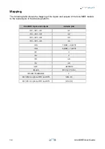
Page 15: ...rduino platform Iono MKR inputs and outputs Arduino pins DI1 AV1 AI1 A1 DI2 AV2 AI2 A2 DI3 AV3 AI3 A3 DI4 AV4 AI4 A4 DI5 7 DEF 0 BYP DI6 5 DEF 1 BYP O1 3 O2 2 O3 A6 O4 A5 AO1 A0 DAC0 RS 485 RX 13 TX 1...

Page 16: ...the case Follow these steps in the exact order to open the case 1 Remove the green pluggable terminal blocks 2 Remove the black plastic DIN rail hook 3 With a small flat screwdriver gently separate t...

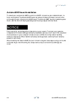
Page 17: ...electricity can damage the components in your system To protect your system s components from static damage during the installation process touch any of the unpainted metal surfaces on your computer...

Page 18: ...nalities to monitor the inputs filtering out possible noise and control the outputs HTTP APIs Modbus support and much more Go to https github com sfera labs to access the code and documentation Progra...

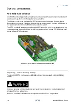
Page 19: ...ves external power The RTC module is based on the Microchip MCP79410 real time clock calendar chip It is connected to the Arduino MKR via the I2C bus address 0x57 for the EEPROM and 0x6f for the SRAM...

Page 20: ...to external devices including USB cables Use a non conductive pin or small tool to help extract the battery from its holder Insert the new battery with a gentle push You don t need tools to insert th...

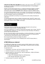
Page 21: ...e optional communication key disablement prior to secure boot Encryption Authentication for messages to prevent on board attacks Internal high quality FIPS 800 90 A B C Random Number Generator RNG Two...

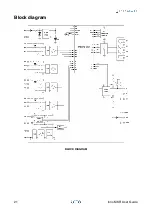
Page 22: ...Block diagram BLOCK DIAGRAM 21 Iono MKR User Guide...

Page 23: ...Board layout BOARD LAYOUT 22 Iono MKR User Guide...

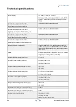
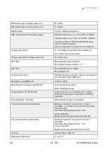
Page 24: ...duino MKR WiFi 1010 Arduino MKR1000 WiFi with headers Arduino MKR ZERO Arduino MKR GSM 1400 Arduino MKR FOX 1200 Arduino MKR WAN 1300 Inputs 4 multi mode digital or analog 0 30V or 0 25mA 2 digital al...

Page 25: ...f duplex with data direction management controlled by Arduino MKR pin 4 Baud Rates on COMM ports 1200 to 115200 ESD Protection Voltage on RS 485 A B 15kV human body model 8kV contact discharge Surge p...

Page 26: ...Storage temperature 20 70 C Relative humidity 5 to 90 noncondensing Protection degree IP20 Weight 128 g Iono MKR 160 g Iono MKR with Arduino MKR1010 WiFi 25 Iono MKR User Guide...

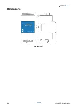
Page 27: ...Dimensions DIMENSIONS 26 Iono MKR User Guide...

Page 28: ...lations The design and the setting up of electrical systems must be performed according to the relevant standards guidelines specifications and regulations of the relevant country The installation con...

Page 29: ...s are designed to provide reasonable protection against harmful interference in a residential installation This equipment generates uses and can radiate radio frequency energy and if not installed and...

Page 30: ...y not cause harmful interference and 2 this device must accept any interference received including interference that may cause undesired operation CANADA This Class B digital apparatus complies with C...

Reviews: