background image

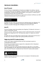
Worn-out or defective batteries can compromise the function of this product.

KEEP OUT OF REACH OF CHILDREN

. Swallowing may lead to serious injury or death in 

as little as 2 hours due to chemical burns and potential perforation of the esophagus. 
Immediately see doctor.

Replace the RTC lithium battery before it is completely discharged. Replace the battery 
every 5 years even if the battery is still working properly. The lithium battery must be 
replaced only with an identical 

CR1025

 Lithium / Manganese Dioxide (Li/MnO2) battery.

Do not throw lithium batteries into fire, do not solder on the cell body, do not recharge, do 
not open, do not short-circuit, do not reverse polarity, do not heat above 100°C and protect 
from direct sunlight, moisture and condensation.

Dispose of used batteries according to local regulations and the battery manufacturer's 
instructions.

The RTC backup battery holder is soldered to a small circuit board next to the GPIO 
connector. In the Iono Pi server, the battery is not accessible from the outside. You should 
first remove the case top body to gain access to the Iono Pi circuit board.

Before opening the Iono Pi case, disconnect all power sources and any connection to 
external devices, including USB cables.

Use a non-conductive pin or small tool to help extract the battery from its holder. Insert the 
new battery with a gentle push. You don't need tools to insert the battery. The battery is 
held into place by a spring contact.

Be sure to insert the battery so that the positive (+) terminal of the battery is in contact with 
the outer body of the battery holder, and the negative (-) terminal is in contact with the 
contact pad of the circuit board, as shown in the photo below.

Reversing the battery polarity may damage the product.

The real time clock will reset its time immediately when the RTC backup battery is 
disconnected.

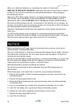
Follow these steps, in the exact order, to open the case and replace the battery:

1. Remove the microSD card (the card will be damaged if you open the case with the 

card still inserted)

2. Remove the black plastic DIN rail hook

3. With a small flat screwdriver gently separate the bottom case and boards assembly 

from the top cover

4. Use a non-conductive pin or small tool to help extract the battery from its holder

5. Insert the new battery with a gentle push. Respect the battery polarity

6. Replace the case bottom applying a gentle pressure on the corners

7. Replace the black plastic DIN rail hook

8. Insert the microSD card.

NOTICE

10

User Guide

Summary of Contents for Iono Pi

Page 1: ...on 006 IPBB13X Iono Pi board IPBB13R Iono Pi RTC board IPMB13X Iono Pi with Raspberry Pi 3 Model B IPMB13R Iono Pi RTC with Raspberry Pi 3 Model B IPMB13XP Iono Pi with Raspberry Pi 3 Model B IPMB13RP...

Page 2: ...puts 15 Ox Relays 16 L1 On board application LED 16 TTL1 1 Wire input output 16 TTLx DIx TTL input output or generic digital inputs 16 OCx DIx Open collector outputs or generic digital inputs 18 Real...

Page 3: ...ety instructions 29 Set up 29 Conformity Information 30 EU 30 USA 30 CANADA 31 AUSTRALIA NEW ZEALAND 31 Compliance information for Raspberry Pi 3 Model B 31 EU 31 USA 31 CANADA 31 Compliance informati...

Page 4: ...Pi is neither designed nor intended for use in critical military or aerospace applications or environments and for automotive applications or environment Customer acknowledges and agrees that any such...

Page 5: ...this product Hazard levels This manual contains information you must observe to ensure your personal safety and prevent damage to property Safety information in this manual are highlighted by the safe...

Page 6: ...t installed and operated properly Follow all applicable electrical safety standards guidelines specifications and regulations for installation wiring and operations of this product The Raspberry Pi bo...

Page 7: ...m battery must be replaced only with an identical battery See the Replacing the RTC backup battery section for instructions Do not throw lithium batteries into fire do not solder on the cell body do n...

Page 8: ...control to home and building automation as well as access control hotel room control solutions environmental monitoring and many others Software development is pure Raspberry Pi with the constantly gr...

Page 9: ...igital input output pins 1 Wire and Wiegand support optional real time clock with replaceable CR1025 Lithium Manganese Dioxide back up battery 2 on board LEDs one for power supply and one controlled b...

Page 10: ...standard DIN rail case There is no need to open the case unless you have to change the position of the jumpers that select the voltage level of the TTL DI inputs see below or to replace the internal b...

Page 11: ...connect all power sources and any connection to external devices including USB cables Use a non conductive pin or small tool to help extract the battery from its holder Insert the new battery with a g...

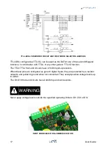
Page 12: ...RTC BACKUP BATTERY Usage and connections IONO PI CONNECTION EXAMPLE 11 User Guide...

Page 13: ...ules highly recommended Recommended stripping length is 5 mm Screw thread is M2 Never exceed 0 25 Nm torque when tightening the screws An 8 positions terminal block on the opposite side for the power...

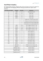
Page 14: ...D TTL1 GPIO4 in out 1 Wire Wiegand or generic TTL I O TTL2 GPIO26 in out 1 Wire Wiegand or generic TTL I O TTL3 GPIO20 in out 1 Wire Wiegand or generic TTL I O TTL4 GPIO21 in out 1 Wire Wiegand or gen...

Page 15: ...vide up to 2 5A at 5V to the Raspberry Pi Because Iono Pi has a 1 1A resettable fuse polyfuse on the power supply line the maximum current that its regulator can deliver is also limited by this fuse a...

Page 16: ...gnals Because the analog inputs are not galvanically isolated from the Iono Pi s power supply the A GND line must be kept at the same voltage level of the negative power supply line VS and the GND con...

Page 17: ...he Raspberry Pi GPIO4 pin through a bidirectional level shifter It can be used as a 1 Wire bus line but can also serve as a generic TTL I O or as the DATA0 line of a Wiegand interface The TTL1 front e...

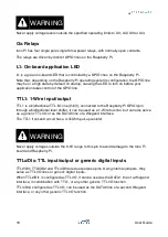
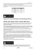
Page 18: ...end circuits have 4 7kOhm pull up resistors When these pins are configured as generic digital inputs they are protected by a resistor network and pulled to ground when not connected They accept positi...

Page 19: ...GPIO pin will reset the protection To drive a load using an OC output connect its positive input to the VSOUT pin and the negative input to the OC pin Note that the input resistors network is permanen...

Page 20: ...Manganese Dioxide Li MnO2 battery installed The battery is only used to power the RTC chip when the main power is not available when the Raspberry Pi is off Depending on operating conditions it should...

Page 21: ...l the Iono Pi utility sudo apt get install git core git clone recursive https github com sfera labs iono pi c lib git cd iono pi c lib sudo sh build You can run the Iono Pi utility without arguments t...

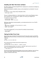
Page 22: ...strato rtc install chmod 755 rtc install sudo rtc install If the script completes with no errors delete the installation script and reboot rm rtc install sudo reboot Testing the Real Time Clock Assum...

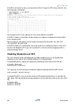
Page 23: ...RTC address is not detected the cause could be a hardware problem on the Iono board or the Raspberry Pi If you have another Pi or Iono board try swapping them to isolate the faulty board Disabling Bl...

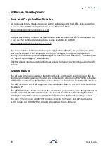
Page 24: ...apping table above Only the analog inputs are connected to an analog to digital converter chip using the SPI protocol Analog inputs The AI1 and AI2 analog inputs on the terminal block and the AI3 and...

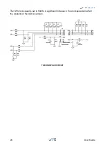
Page 25: ...The SPI clock speed is set to 50kHz A significant increase in the clock speed will affect the reliability of the A D conversion THE IONO PI A D CIRCUIT 24 User Guide...

Page 26: ...Block diagram IONO PI BLOCK DIAGRAM 25 User Guide...

Page 27: ...GPU load 75mA unconnected inputs relays OFF 135mA inputs connected to VSOUT relays ON High CPU GPU load 170mA unconnected inputs relays OFF 225mA inputs connected to VSOUT relays ON Actual current con...

Page 28: ...AUX VSOUT Max allowable current 300mA Min voltage Supply voltage 1V AUX 5VOUT Max allowable current 50mA Min voltage 4 5V Real time clock Iono Pi RTC version only Internal RTCC circuit with backup li...

Page 29: ...Dimensions DIMENSIONS mm 28 User Guide...

Page 30: ...top body to gain access to the Iono Pi circuit board Always remove the battery before disposing of this product Installation and use restrictions Standards and regulations The design and the setting...

Page 31: ...ns may cause harmful interference to radio communications However there is no guarantee that interference will not occur in a particular installation If this equipment does cause harmful interference...

Page 32: ...o provide a separation distance of at least 20 cm from all persons and must not be colocated or operating in conjunction with any other antenna or transmitter except in accordance with FCC multitransm...

Page 33: ...r except in accordance with FCC multitransmitter product guidelines This WiFi DTS device has 20 MHz bandwidth mode CANADA Raspberry Pi 3 Model B IC CERTIFICATION No 20953 RPI3P This device complies wi...

Page 34: ...0002700 G88104401 GUR02 OACU C4SWOUT PB16H SM IDC15 G34960001700 G77 S G78 16 E GP34829091724 GP34960005700 JQP4 ODC 24A IDC5P FC6A N16B1 6421 FC6A N32B3 70MRCQ32 HL C200H LK201 V1 G3TA OA202SZ US DC1...

Reviews: