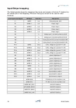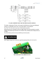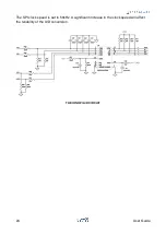
To use the TTLx/DIx lines as generic inputs, the corresponding jumper (see table below)
should be set across the two pins closer to the terminal block.
Set the jumpers across the center and the pin opposite the terminal block to use the input
as TTL I/O.
Note that the Iono Pi board and the Raspberry Pi could be damaged if the jumpers are
configured for TTL mode and voltages outside the 0÷5V range are applied to the inputs.
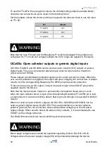
OCx/DIx: Open collector outputs or generic digital inputs
OC1/DI4, OC2/DI5 and OC3/DI6 can be used as open collector (OC) outputs or generic
digital inputs. They are connected to discrete open collector drivers with a maximum
output current of 100mA.
These outputs are individually protected against over-current and short circuits. When the
over-current protection is triggered, the output will open, stopping the current flow. A simple
reset to 0 of the corresponding Raspberry Pi’s GPIO pin will reset the protection.
To drive a load using an OC output, connect its positive input to the VSOUT pin and the
negative input to the OC pin.
Note that the input resistors network is permanently connected to these pins so, even
when the open collector driver is open (the corresponding Raspberry Pi’s GPIO pin is low),
a small amount of current will still be able to flow to ground through an equivalent 6.9kOhm
resistor.
When not used as open collector outputs, the OC1/DI4, OC2/DI5 and OC3/DI6 can be
used as generic digital inputs, like DI1-DI3. They are protected by a resistor network,
pulled to ground when not connected, and accept positive voltage up to the VS power
supply voltage. When used to detect the status of dry contacts, it is recommended to use
VSOUT as the voltage reference.
The DI4-DI6 front-end circuits have 2.2kOhm pull-down resistors.
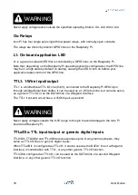
Never apply voltage levels outside the specified operating limits to DI4, DI5 or DI6.
Voltages above the power supply voltage (VS) will permanently damage the device.
Pin
Jumper
TTL2/DI1
JP3
TTL3/DI2
JP2
TTL4/DI3
JP1
WARNING
WARNING
18
User Guide

