Power supply
Iono RP D16 can be powered with DC voltage only.
The device is split in two distinct and galvanically isolated sections, the control logic
section and the digital input/output section.
Control logic section
✓
DC: nominal voltage between 12
V and 28
V (min=10
V, max=30
V)
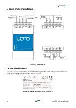
Respect the correct polarity shown in the schematic diagram (+ -). The power supply
circuit implements reverse polarity protection using an auto resetting fuse and surge
protection up to ±500
V/2
Ohm 1.2/50
μ
s.
Digital input/output section
✓
DC: nominal voltage between 12
V and 28
V (min=10.5
V, max=36
V)
Respect the correct polarity: ground connected to IGND and positive voltage level to IVINL
and IVINH. IVINL and IVINH can be supplied with different voltages.
IVINL powers the D1-D8 outputs, while IVINH separately powers the D9-D16 outputs.
IVINL and IVINH are not required for the inputs. If all D1-D8 lines are used as inputs, IVINL
should be left unconnected. If all D9-D16 lines are used as inputs, IVINH should be left
unconnected. The IGND connection is always required.
IGND, IVINL and IVINH are each available at two adjacent terminals on the terminal
blocks. Always connect both terminals to the appropriate lines, as a significant amount of
current may flow through these lines.
Auxiliary voltage outputs
Iono RP D16 has an auxiliary 5
Vdc voltage output pin on the terminal block, labeled
5VOUT, to supply power to external 1-Wire devices or other low-power loads. This output
implements an overcurrent protection circuit, with a typical maximum current of 420
mA.
When 5VOUT is turned off because the overcurrent threshold has been exceeded, it is
automatically turned back on when the load is removed.
Another auxiliary voltage output pin, labeled VSOUT, is also available on the terminal
block. It is intended as the voltage source for small loads and dry contacts connected to
the digital inputs. Its typical output voltage is VS - 1
V. Do not exceed the maximum rated
current of 300
mA on this output.
D1-D16 digital inputs
Iono RP D16 has two banks of current-sinking 24
V IEC 61131-2 compliant industrial
digital inputs, based on two MAX22190 integrated circuits, connected to D1-D8 and D9-
D16 terminals. Wire-break detection can be enabled individually on each input line.
The MAX22190 chips are controlled by the RP2040 via its SPI serial bus, chip-select lines,
a latch line and a shared fault line.
All these control lines are galvanically isolated from the RP2040 logic section.
10
Iono RP D16 User Guide

