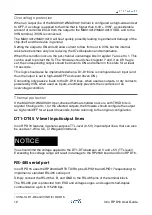
The RS-485 TX/RX switching is controlled by a digital output pin of the RP2040 (GPIO14).
You should set GPIO14 low to enable transmission on the RS-485, and set it high to allow
reception of incoming data.
If GPIO14 is left high, or not configured as output during transmission, the Iono RP D16
RS-485 driver will automatically drive the RS-485 lines in the dominant state, so that it is
not strictly required to control GPIO14 in order to transmit data.
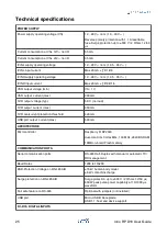
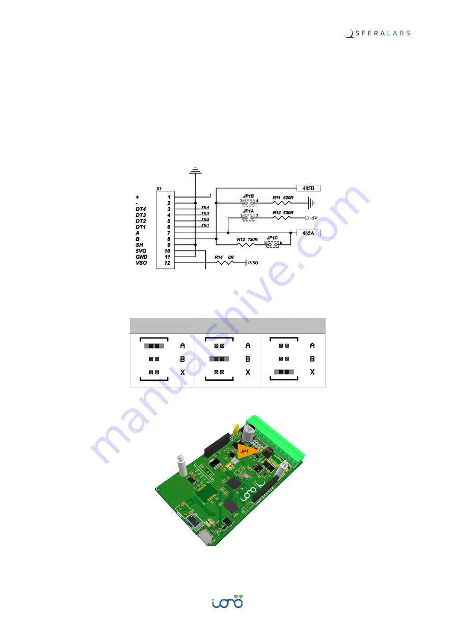
The RS-485 line has 620 Ohm pull-up and pull-down resistors on lines A and B. The
biasing resistors ensure that, during idle periods the data lines are kept at a stable voltage
level and prevent false triggering of receiver input. A 120 Ohm termination resistor
between A and B can also be enabled.
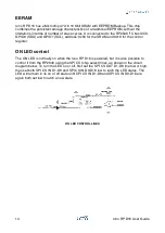
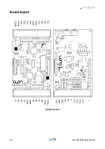
RS-485 JUMPERS SCHEMATIC
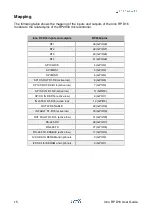
These resistors can be enabled installing jumpers on JP1 according to the following table.
RS-485 JUMPERS POSITION
A PULL-UP
B PULL-DOWN
TERMNATION
13
Iono RP D16 User Guide

