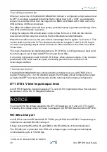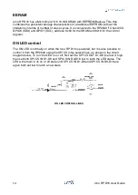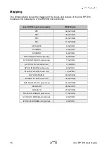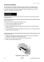
The latch line can be used to synchronize input data on both input banks.
The fault line is asserted (low) on various, configurable, fault conditions, including wire-
break.
Refer to the MAX22190 data sheet for the complete specifications of the digital input lines.
D1-D16 digital outputs
Iono RP D16 has two banks of 24
V outputs that can be configured as high-side switches
or push-pull drivers for high-speed switching, based on two MAX14912/MAX14913
integrated circuits, connected to D1-D8 and D9-D16 terminals. Open-load detection in
high-side mode detects open-wire conditions in the switch on/off states. Internal active
clamps accelerate the shutdown of inductive loads in high-side mode. Other diagnostic
and protection features include per chip and individual line thermal shutdown, overvoltage
detection, and overcurrent detection.
The MAX14912/MAX14913 chips are controlled by the RP2040 via its SPI serial bus, chip-
select lines, a watchdog enable line, and a shared fault line.
The watchdog enable line is pulled high (enabled), so that the MAX14912/MAX14913
watchdog logic is normally active. It can be driven low by the RP2040 to disable the
watchdog if needed.
The fault line is asserted (low) on various fault conditions, including open-load.
All these control lines are galvanically isolated from the RP2040 logic section.
Refer to the MAX14912/MAX14913 data sheet for the complete specifications of the digital
output lines.
D1-D16 connection and protection
Besides the diagnostics and protection mechanisms implemented in the MAX14912/
MAX14913 output drivers, additional protections should be implemented in the RP2040 to
prevent overheating and permanent damage in specific conditions. Two of these
conditions are discussed below.
These protection mechanisms are implemented in the standard libraries provided by Sfera
Labs (see the "Software development" chapter). If the user's firmware does not use the
provided libraries, it shall implement the protection logic described below.
Some use cases may require the implementation of different or additional protection logic,
or be subject to other electrical and operational limitations.
If the IVINL lines are connected, never apply voltages higher than IVINL to the D1-D8
lines.
If the IVINH lines are connected, never apply voltages higher than IVINH to the D9-D16
lines.
WARNING
11
Iono RP D16 User Guide

