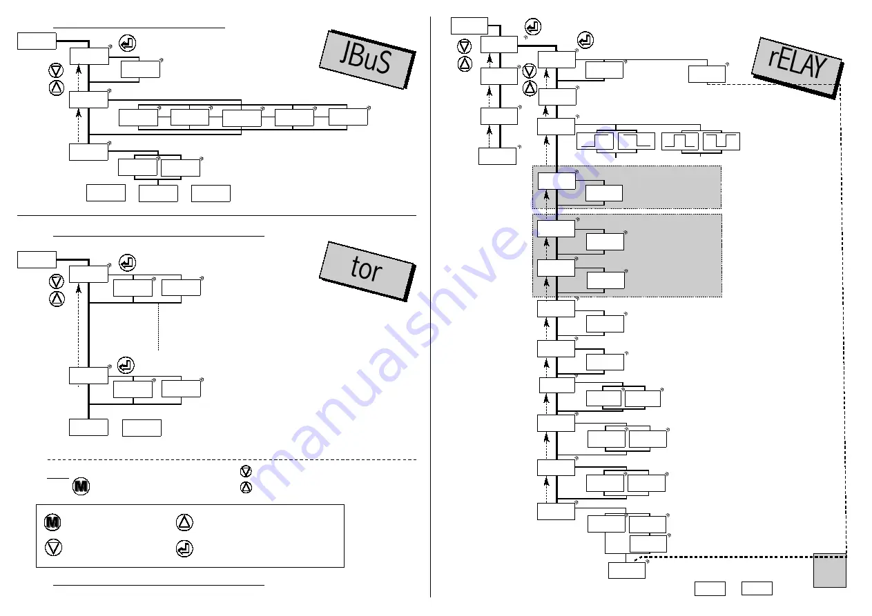
4.4.4 Digital output programming
4.4.5 Programming of the LOGIC inputs
4.4.6 Programming of the relay outputs
slave number
must be included between 1 and
255
transmission speed
function
display
hold
function
min. and
max. zero
reset
SLAvE
-8888
bAUd
9600
4800
2400
1200
19200
tor
rELAY
SECU
or
or
or
rELAY
SECU
HoLd
CLr.M
Note :
Press to go on to next menu
Move through menus / choice
delay before any response pattern
OFF : delay 20ms
On : delay 75ms
On
OFF
dELAY
See also the features of the
digital data link
p11
See also the features of the LOGIC input
p11
Option LOGIC inputs
Option LOGIC inputs
HoLd
CLr.M
tor 1
tor 2
JBuS
tor
Downwards move /
decrease
Validation / Vertical move
Menu exit /access
Upwards move / increase
Option digital output
Option digital output
p8
p8
rEL.1
rELAY
Acti.1
On
ModE.1
PArA.1
SP 1
02.00
HYSt.1
00.00
tiME.1
000.0
LEd 1
SP1.1
02.00
SP1.2
04.00
rEL.3
rEL.4
hysteresis
decimal point + unit
0 < tIME < 025.0
in 0.1s increases
latching function
function display of the alarm message
enter 4 char the point
If option 2 relays, at end of menu REL.2,
if option 4 relays, at end of menu REL.4
access to or
choice of the state of the relay
associated Led
ON
: led lit when relay active
OFF
: led still when relay active
time delay on the relay
SPI.2 must be
≥
SPI.I
active
choice of the parameter dedicated to the output
alarm
idem
rEL.1
idem
rEL.1
idem
rEL.1
de-activated
mode window
mode setpoint
access to SP1
access to SP1.1
OFF
On
MEM.1
no
YES
MESSI
no
AbCd.
rEL.2
SECU
Pr.diS
YES
choice of
the relay
operating
mode : mode
setpoint or
window
(see p14)
(5)
(5)
See also the
features of the
relay ouputs
p11
Option output 2 or 4 relays
Option output 2 or 4 relays
OFF
if mode window programmed
if mode setpoint programmed
rEL.2
(dec. point + unit)
(dec. point + unit)
(dec. point + unit)
if time.1
≠
0. Programming of the location of the
relay time delay.
t.Act.1
SiMPL
doubl


