background image


VACUUM LEAK DETECTOR 

VLXE .. Ex M and VLXE .. Ex MMV

             28/07/2020


- 38 - 

(4)  The test is considered passed if the vacuum does not drop by 

more than 1 mbar during the test period. 
Of course, a multiple of the test period can also be measured; in 
this case, the permissible vacuum drop is also a multiple. 

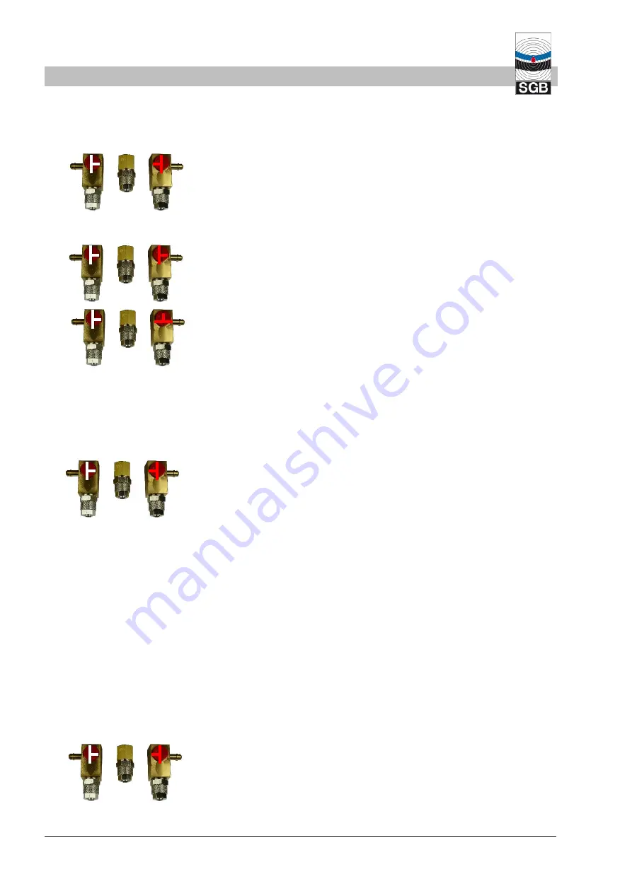
(5)  Once the test is complete, return valves to their original positions 

and remove the measuring gauge. 


7.3.7  Checking the excess pressure alarm (only for version VLXE .. Ex MMV) 

(1)  Attach excess pressure testing device to connection on three-

way valve 21 and turn valve 180°. 


(2)  Then turn three-way valve 21 90°. 

(3)  Apply pressure using the excess pressure testing device. First 

the pumps are switched on, then the alarm is triggered (red LED 
on), and if the pressure continues to increase, the excess pres-
sure alarm is triggered (yellow LED flashes). 

(4)  With the overpressure alarm, the pump halts and the solenoid 

valve switches.  

(5)  Relieve excess pressure by detaching the excess pressure test-

ing device. This alarm goes out and the pump runs; the solenoid 
valve opens. 

(6)  Once the test is complete, return valves to their original positions 

and remove the measuring gauge. 


7.3.8  Checking the additional pressure switch in conjunction with VLXE .. Ex MMV 

(1)  Connect the testing device as per Section 7.3.5 and complete 

steps (1) to (5). 

(2)  Close shut-off cock on the interstitial space side. 

(3)  Connect an external pressure booster to connection 82 and open 

the relevant valve. 

(4)  Pressure build-up until activation of the pressure switch (probe 

alarm is triggered and the solenoid valve switches). 

(5)  Check the corresponding alarm. 

(6)  Relieve pressure; probe alarm goes out and the solenoid valve 

switches. 

(7)  Close the shut-off cock at 82 and remove the pressure booster. 

(8)  Open the shut-off cock on the interstitial space side, put three-

way valves 20 and 21 into operating position, and remove testing 
device. 


21 

20 

21 

20 

Functional Check and Maintenance 

21 

20 

21 

20 

21 

20 

Summary of Contents for VLXE Ex M Series

Page 1: ...Documentation Explosion protected vacuum leak detector VLXE Ex M and VLXE Ex MMV TÜV A 19 ATEX 1119 X Please read instructions prior to commencing any work Last updated 07 2020 Art No 602422 ...

Page 2: ...2 Normal operating condition 13 4 3 Air Leaks 14 4 4 Liquid Leaks 14 4 5 Pressure increase above atmospheric pressure in in terstitial space when using a VLXE MV Ex acc to chapter 3 5 1 f as well as 3 5 2 14 4 6 Displays and Controls 15 5 Mounting the System 17 5 1 Basic Instructions 17 5 2 Assembly of the Leak Detector 17 5 3 Pneumatic Connection Lines 18 5 4 Completing Pneumatic Connections 20 5...

Page 3: ...pendix 42 12 1 Use of Interstitial Spaces That Are Filled with Leak Detector Fluid 42 12 2 Appendix W Warmed Tanks Heated Tanks 43 12 3 Dimensions and Drilling Pattern 46 12 4 Declaration of Conformity 47 12 5 Declaration of Performance 48 12 6 Declaration of Compliance of the Manufacturer 48 12 7 Ex approval 49 12 8 Certification TÜV Nord 53 Contents ...

Page 4: ... result in death or serious injury WARNING Potentially hazardous situation which if not avoided could result in death or serious injury CAUTION Potentially hazardous situation which if not avoided could result in minor or moderate injury Information Highlights useful tips recommendations and information 1 3 Limitation of Liability All information and instructions in this documentation have been co...

Page 5: ...l number of the leak detector must be stated The obligation of warranty shall cease to exist in the case of inadequate or improper installation improper use modifications repairs without consent of the manufacturer Our warranty does not include parts which may be perished prema ture due to their consistence or category of usage e g pumps valves gaskets etc Furthermore we are not liable for defects...

Page 6: ...ply cannot be disconnected Ground main voltages shall be at the same potential as the equi potential bonding of the tank pipelines Any claims arising from misuse are excluded 2 2 Obligation of the Operating Company Leak detector VLXE Ex M and VLXE Ex MMV are used in the commercial sector The operating company is therefore subject to statutory occupational safety obligations In addition to the safe...

Page 7: ...omply with existing PPE signs For further information see 2 4 1 Entry in the Safety Book Wear HV vest Wear safety footwear Wear hard hat Wear gloves where necessary Wear safety goggles where necessary 2 4 1 Personal protective equipment for systems that may be subject to risk of explosion The parts listed here refer in particular to safety when working with systems that may be subject to risk of e...

Page 8: ...e disconnected from the power supply DANGER From explosive vapor air mixtures Explosive vapor air mixtures can exist in the leak detector and in the connection lines Ensure there is no gas present prior to performing work Comply with explosion regulations e g German Ordinance on Indus trial Safety and Health Betriebssicherheitsverordnung BetrSichV and or directive 1999 92 EC and the laws of the re...

Page 9: ...11 13 potential free DC 25 W or AC 50 VA Fuse protection max 2 A 1500 A Overvoltage category 2 3 3 EX data Leak detector II 1 2 2 G Ex db eb ib ib Gb mb IIB H2 T4 Ga Gb with F 501 II 1 2 2 G Ex db eb ib ib Gb mb IIB3 T4 Ga Gb with F 502 II 1 2 2 G Ex db eb ib ib Gb mb IIC T4 Ga Gb 3 4 Switching Values Type Alarm ON at the latest Pump OFF not more than Functionality of the interstitial space given ...

Page 10: ...suction line to low point Usage limits Density of the stored material kg dm3 Hmax Tank height or height of the low point of the pipe lines to the node point2 m 230 255 330 410 500 570 0 8 2 6 2 9 3 8 4 8 6 0 6 9 0 9 2 3 2 6 3 4 4 3 5 3 6 1 1 0 2 0 2 3 3 1 3 9 4 8 5 5 1 1 1 9 2 1 2 8 3 5 4 4 5 0 1 2 1 7 1 9 2 6 3 2 4 0 4 6 1 3 1 6 1 8 2 4 3 0 3 7 4 2 1 4 1 5 1 6 2 2 2 8 3 4 3 9 1 5 1 4 1 5 2 0 2 6 ...

Page 11: ...1 9 2900 8400 0 9 1 9 1 9 1 9 9585 0 9 1 9 1 9 1 9 12 750 0 8 1 2 1 2 1 6 15 950 1 0 1 0 1 2 d Rectangular or cylindrical tanks or troughs with a flat bottom dou ble walled or with leak detection lining or leak detection jacket with a suction line to the low point Density of the stored material kg dm3 Hmax m 34 230 255 330 410 500 570 0 8 7 5 17 3 19 1 23 4 23 8 24 5 24 2 0 9 6 6 15 3 17 0 20 8 21...

Page 12: ... pressure of up to 25 bar Version VLXE 230 Ex MMV to VLXE 570 Ex MMV Pressure lines with feed pressure of up to 90 bar Version VLXE 230 Ex MMV to VLXE 570 Ex MMV only in con junction with an additional pressure switch combined with sole noid valve In particular applications single pipe gradient to a point the ver sion VLXE 34 Ex Mcan also be used For Germany with proof of usability from constructi...

Page 13: ...ion line s The vacuum generated by the pump is measured and controlled by a pressure sensor When the operating vacuum is reached Pump OFF the pump shuts off The vacuum slowly drops due to slight unavoidable leaks in the leak detector system When the Pump ON switching value is reached the pump turns on and the interstitial space is evacuated until the op erating vacuum is reached Pump OFF In normal...

Page 14: ...ne and if applicable into a pressure compensation vessel This causes the vacuum to drop until the Alarm ON pressure is reached This triggers the visual and audible alarms Comment It is also an option to use a liquid sensor in conjunction with a solenoid valve instead of the liquid stop valve The liquid alarm is then triggered when the sensor comes into contact with liquid 4 5 Pressure increase abo...

Page 15: ...Mute button for about 10 seconds The alarm will be triggered until the key is released This inquiry is only possible if the pressure in the system has exceed ed the Alarm OFF pressure 3 Flashing is active for the acknowledged external signal 4 The Mute button does not have a function which means the audible signal cannot be turned off Indicator light Operating condi tion Alarm vacuum below Alarm O...

Page 16: ...matic refilling interval under normal operating condition i e without external filling e g by an installation pump to achieve a valid statement This inquiry is recommended before performing a regular functional check of a leak detector In this way it is possible to estimate imme diately whether it is necessary to look for leaks Number of flash signals Assessment of tightness 0 Very tight 1 to 3 Ti...

Page 17: ...pection chambers the oxygen content must be tested and the inspection chamber flushed if necessary If metallic connection lines are used it must be ensured that the power supply grounding is on the same potential as the pipe line tank to be monitored 5 2 Assembly of the Leak Detector Wall mounting using the supplied mounting material Outside and inside the Ex area zone 1 or 2 in the open air with ...

Page 18: ...he interstitial space 5 3 2 Exhaust The length of the exhaust line must not exceed 35 m If these lengths are not sufficient consult the manufacturer The exhaust line is generally routed to the tank ventilation in which case a denotation flame arrester must be installed directly before the connection on the tank vent side Exceptions to the return of the exhaust to the tank ventilation Tanks with in...

Page 19: ...7 4 and 5 7 5 Length of the measuring line from the pressure compensation ves sel V 0 1 l 8 Type 230 330 Lmax 16 m Type 410 Lmax 12 m Type 500 Lmax 10 m Type 570 Lmax 8 m CAUTION The bottom edge of the pressure compensation vessel must not be lower than the node point the upper edge of the pres sure compensation vessel must not end more than 30 cm above the node point For each 10 ml of the condens...

Page 20: ... again that they are protect ed against damage when the manhole chamber is entered 3 Complete the relevant connection according to the illustrations in the following images 5 4 3 1 Flanged screw connection for flanged pipes 1 Lubricate O rings 2 Insert spacer ring loosely into the screw socket 3 Slide union nut and pressure ring over the pipe 4 Hand tighten union nut 5 Tighten union nut until need...

Page 21: ...panies 3 Terminal layout see also SL 854 310 1 2 Power connection 100 240 V AC PE Ground for the power connection PA Terminals for equipotential bonding 3 4 Occupied vacuum pump 5 6 External signal may be used for internal buzzer 7 8 Solenoid valve 9 10 Probe contacts the potential free contacts of a leak de tection probe can be connected here 11 12 Potential free contacts opened in case of alarm ...

Page 22: ...or in the housing wall through the housing The customer can now connect the BM i to the display unit indicating unit DDU via a bus supply isolator BST For more details on the connection and the intrinsic safety certifica tion refer to the DDU and BST documentation 5 6 3 Potential equalization The housing of the leak detector must be connected to the equipo tential bonding of the overall system by ...

Page 23: ...filling 60 Pump 24 V DC 69 Buzzer if installed 76 Main board 90 Temperature switch 91 Heating 102 Pressure sensor 103 Display 105 Control unit 116 Power supply unit 24 V DC 139 Keypad 140 Contacts for serial data transfer 141 Keypad terminal strip 146 Solenoid valve monitoring board 165 Separating barrier TBI 166 TBI adapter to 76 169 Data bus module BM i Mounting Surfaces yellow ex de green ex db...

Page 24: ... and suction line to low point 02 Shut off cock 03 Exhaust 18 Denotation flame arrester 20 Three way valve suction line 21 Three way valve measuring line 27 Liquid stop valve 43 Measuring line 68 Suction line 73 Interstitial space 82 Nozzle for assembly pump 101 Suction line to low point Ex Ex 73 73 101 101 20 21 68 43 03 43 68 18 27 02 82 Mounting ...

Page 25: ...teel without suction line to low point 02 Shut off cock 03 Exhaust 18 Denotation flame arrester 20 Three way valve suction line 21 Three way valve measuring line 27 Liquid stop valve 43 Measuring line 68 Suction line 73 Interstitial space 82 Nozzle for assembly pump 73 18 68 03 43 H max 27 02 82 20 21 Mounting ...

Page 26: ...wnwards outside suction line 02 Shut off cock 03 Exhaust 18 Denotation flame arrester 20 Three way valve suction line 21 Three way valve measuring line 27 Liquid stop valve 33 Condensate trap 43 Measuring line 68 Suction line 73 Interstitial space 82 Nozzle for assembly pump 73 101 68 03 43 33 18 H max 27 02 82 20 21 Mounting ...

Page 27: ...st 18 Denotation flame arrester 20 Three way valve suction line 21 Three way valve measuring line 27 Liquid stop valve 27 Liquid stop valve connected against the flow direction 33 Condensate trap 43 Measuring line 44 Solenoid valve 57 Test valve 68 Suction line 74 Connection line 82 Nozzle for assembly pump 88 Double walled pipe 95 Pressure compensation vessel 96 Node point 88 68 27 27 96 74 02 18...

Page 28: ... Shut off cock 03 Exhaust 18 Denotation flame arrester 20 Three way valve suction line 21 Three way valve measuring line 27 Liquid stop valve 27 Condensate trap 43 Measuring line 44 Solenoid valve 57 Test valve 68 Suction line 74 Connection line 82 Nozzle for assembly pump 88 Double walled pipe 95 Pressure compensation vessel 96 Node point 148 Additional pressure switch 88 68 27 96 148 74 18 02 95...

Page 29: ... way valve suction line 21 Three way valve measuring line 27 Liquid stop valve 27 Liquid stop valve connected against the flow direction 43 Measuring line 44 Solenoid valve 57 Test valve 68 Suction line 74 Connection line 82 Nozzle for assembly pump 88 Double walled pipe 95 Pressure compensation vessel 96 Node point 88 68 27 27 96 74 02 18 95 43 57 H max H max H max bar bar bar 20 21 H max Mountin...

Page 30: ...lve suction line 21 Three way valve measuring line 27 Liquid stop valve 27 Liquid stop valve connected against the flow direction 43 Measuring line 44 Solenoid valve 57 Test valve 68 Suction line 74 Connection line 82 Nozzle for assembly pump 88 Double walled pipe 95 Pressure compensation vessel 96 Node point 88 27 18 18 82 02 02 0 H max V V ÜR 1 ÜR 2 68 27 95 43 20 21 Mounting ...

Page 31: ...way valve suction line 21 Three way valve measuring line 27 Liquid stop valve 43 Measuring line 57 Test valve 68 Suction line 74 Connection line 88 Double walled pipe 95 Pressure compensation vessel 96 Node point Here must geodetically be under 157 157 Lowest point of the interstitial space 88 68 27 96 74 27 157 18 95 43 57 20 21 VLXE 34 Ex 0 3 m Mounting ...

Page 32: ...al space volume divided by 10 E g The test period for an interstitial space volume of 800 liters is 800 10 80 minutes Within this test period the vacuum must not fall below 1 mbar 6 2 Commissioning the Leak Detector 1 Tightness of the interstitial space prior to commissioning is as sumed 2 Connect voltage supply 3 Ascertain lighting of Operation and Alarm indicator lights and sounding of the audib...

Page 33: ...20 Turn valve 180 and switch on the assembly pump 7 After the operating vacuum of the leak detector has been reached pump in leak detector shuts off turn three way valve 20 180 switch off the assembly pump and remove it 8 Turn three way valve 21 180 and remove the pressure measur ing gauge 9 Perform a functional check according to Section 7 3 21 20 21 20 Commissioning ...

Page 34: ...ssure 7 CAUTION For single walled tanks equipped with a flexible leak detector lining the interstitial space can never be without pres sure collapse of the leak protection lining 8 To clean the leak detector use a moist cloth electrostatic 7 2 Maintenance o Maintenance work and functional checks must be performed by trained personnel only9 o Once a year to ensure functional and operational safety ...

Page 35: ...m only for version VLXE Ex MMV 7 3 7 Checking the additional pressure switch in conjunction with VLXE Ex MMV 7 3 8 Testing of the probe only VLXE Ex MMV LS 7 3 9 Creating the operating condition 7 3 10 A test report must be completed confirming functional and opera tional safety Test reports are available for download for the SGB website 7 3 1 Checking and emptying the condensate traps if required...

Page 36: ...titial spaces the leak detector side shut off cocks of the interstitial spaces not included in the test can be closed For tanks Turn three way valve 20 90 clock wise so that the suction line and system are ventilated 3 Check switching values Pump ON and Alarm ON with visual and audible if available Record the values 4 Press the Audible alarm button if necessary 5 Return three way valve 20 to its o...

Page 37: ...g the operat ing vacuum in the interstitial space 1 Attach measuring gauge to connection on three way valve 20 and turn valve 90 CCW 2 The pump is usually not running at this moment i e the pres sure sensor must be vented to start the pump 3 Turn three way valve 21 90 CW The pressure sensor is vent ed the pump starts and the alarm is triggered acknowledge if necessary 4 This unit passes the test i...

Page 38: ...p halts and the solenoid valve switches 5 Relieve excess pressure by detaching the excess pressure test ing device This alarm goes out and the pump runs the solenoid valve opens 6 Once the test is complete return valves to their original positions and remove the measuring gauge 7 3 8 Checking the additional pressure switch in conjunction with VLXE Ex MMV 1 Connect the testing device as per Section...

Page 39: ... test 2 Check probe alarm as per Section 4 6 1 and the switching of the solenoid valve 3 Establish the probe operating condition again the probe alarm goes out and the solenoid valve opens 7 3 10 Achieving the Operating Condition 1 Test if all pneumatic connections are completed 2 Check that the three way valves are in the correct position 3 Seal the housing 4 Seal the shut off cocks between the l...

Page 40: ...pany 6 The installation company must detect the cause and correct it CAUTION Depending on the tank pipelines there could be liquid under pressure in the connection lines CAUTION Do not depressurize the interstitial space in the tanks with flexible leak protection lining risk of collapse of the insert 7 Repairs to the leak detector e g replacement of components may only be made outside the ex area ...

Page 41: ... contains sufficient oxygen levels Seal any openings through which an explosive atmosphere can carry over so they are gas tight Avoid using spark producing tools saws parting grinders etc for disassembly whenever possible Should this be unavoidable howev er comply with EN 1127 or the area must be free of explosive atmos phere Avoid the build up of electrostatic charges e g through friction 11 2 Di...

Page 42: ...on of the assembly pump to a tank11 socket with intermediately connected tanks Suction out until no more liquid is being suctioned Assembly of a large shut off cock at least on the other connection and close the shut off cock Pump out liquid until no more liquid comes into the intermedi ate tanks Suddenly open shut off cock with pump running so that a fur ther surge of leak detecting fluid enters ...

Page 43: ... connection line between the leak detector and the tank c The leak detector including the solenoid valve s must be installed so that the ambient temperature does not exceed 55 C e g radi ant heat of the tank d The process temperature for the sensor can be up to 200 C the ambient temperature must not exceed 70 C clarification with SGB GmbH on a case by case basis e If the sensor used is approved as...

Page 44: ...icator light green 18 Denotation flame arrester 20 Three way valve in suction line 21 Three way valve in the measuring line 33 Condensate trap 43 Measuring line 44 Solenoid valve 68 Suction line 69 Buzzer if installed 71 Mute button 73 Interstitial space 82 Connection assembly pump 97 Probe 101 Suction line to low point 111 Cooling line 112 Isolation 02 02 97 18 82 101 111 111 112 73 33 68 43 03 E...

Page 45: ...ester 20 Three way valve in suction line 21 Three way valve in the measuring line 33 Condensate trap 43 Measuring line 44 Solenoid valve 68 Suction line 69 Buzzer if installed 71 Mute button 73 Interstitial space 82 Connection assembly pump 95 Pressure compensation vessel here mounted inside the isolation i e needs to be warm due to fluidity 97 Probe 101 Suction line to low point 111 Cooling line ...

Page 46: ...VACUUM LEAK DETECTOR VLXE Ex M and VLXE Ex MMV 28 07 2020 46 12 3 Dimensions and Drilling Pattern Appendix 350 305 50 40 280 323 8 5 400 ...

Page 47: ...61 000 3 2 2015 EN 61 000 3 3 2014 2014 34 EU Equipment for EX Areas Named location with identifier The pneumatic components of the leak detector may be connected to spaces interstitial spaces of pipelines fittings that require cate gory 1 devices The following documents have been consulted TÜV A 19 ATEX 1119 X with EN 60079 0 2012 corr 2013 EN 60079 1 2014 EN 60079 7 2015 EN 60079 11 2012 EN 6007...

Page 48: ...ndard EN 13160 1 2 2003 Notified body TÜV Nord Systems GmbH Co KG CC Tankanla gen Große Bahnstraße 31 22525 Hamburg Germany Identification number of the notified testing laboratory 0045 7 Declared performance Essential characteristics Performance Harmo nized standard Electrical function corresponds to documentation EN 13160 2 2003 Operating alarm signal light green red Tightness test 1 Pa l s Pres...

Page 49: ...28 07 2020 VACUUM LEAK DETECTOR VLXE Ex M and VLXE Ex MMV 49 12 7 Ex approval Appendix ...

Page 50: ...VACUUM LEAK DETECTOR VLXE Ex M and VLXE Ex MMV 28 07 2020 50 Appendix ...

Page 51: ...28 07 2020 VACUUM LEAK DETECTOR VLXE Ex M and VLXE Ex MMV 51 Appendix ...

Page 52: ...VACUUM LEAK DETECTOR VLXE Ex M and VLXE Ex MMV 28 07 2020 52 Appendix ...

Page 53: ...28 07 2020 VACUUM LEAK DETECTOR VLXE Ex M and VLXE Ex MMV 53 12 8 Certification TÜV Nord Appendix ...

Page 54: ...VACUUM LEAK DETECTOR VLXE Ex M and VLXE Ex MMV 28 07 2020 54 Appendix ...

Page 55: ...____________________________________________________________________________________ ______________________________________________________________________________________ ______________________________________________________________________________________ ______________________________________________________________________________________ ______________________________________________________...

Page 56: ...E Ex MMV 28 07 2020 56 Text Text Legal notice SGB GmbH Hofstr 10 57076 Siegen Germany T 49 271 48964 0 E sgb sgb de I www sgb de Photos and sketches are not binding for the scope of delivery Subject to change without notice SGB GmbH 07 2020 ...

Reviews: