S G - 23 7 S m ar t un er ™ M anual
SGC, 13737 SE 26
th
Street Bellevue, WA 98005 USA • Ph: 425-746-6310, Fx: 425-746-6384, Email: sgc@sgcworld.com
www.sgcworld.com
SGC RESERVES THE RIGHT TO CHANGE SPECIFICATIONS WITHOUT NOTICE
Copyright SGC 2008
2
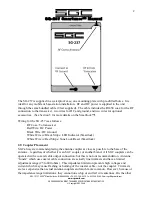
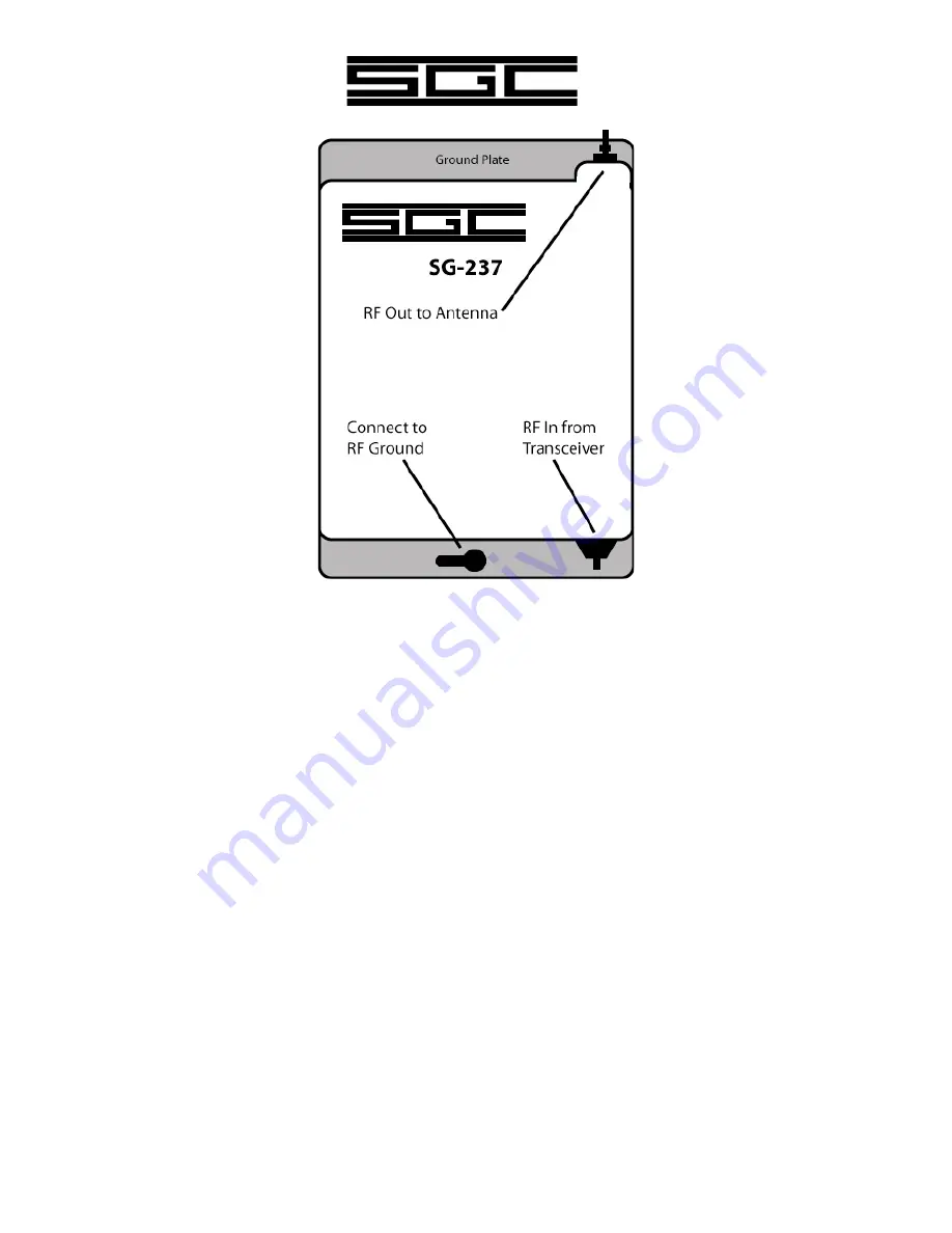
The SG-237 is supplied in a waterproof case, on a mounting plate with pre-drilled holes. It is
ideal for any mobile or base-station installation. RF and DC power is supplied to the unit
through the same bundled cable (9 feet supplied). The cable includes the RG-58 coax for the RF
connection to the transceiver, two wires for DC and ground, and two wires for optional
accessories. (See Section 5 for more details on the Smartlock™).
Wiring for the SG-237 is as follows:
RF Coax: To transceiver
Red Wire: DC Power
Black Wire: DC Ground
White Wire w/ Black Stripe: LED Indicator (Smartlock)
White Wire w/ Red Stripe: Tune Lock/Reset (Smartlock)
2.0
Coupler Placement
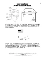
SGC always recommends placing the antenna coupler as close as possible to the base of the
antenna – regardless of whether it is an SGC coupler or another brand. All SGC couplers can be
operated with a coaxial cable output connection; but this is not our recommendation. Antenna
“tuners” which use coaxial cable connection are actually line trimmers and have a limited
adjustment range (25 to 800 ohms). This impedance limitation prevents high voltages and
current which may cause flashing or burning of the coaxial cable – not the coupler. Trimmers
are less expensive than actual antenna couplers and much more common. However, because of
the impedance range limitations, they cannot tune whip or end fed wire antennas. On the other


