Page 11 of 40
METER -
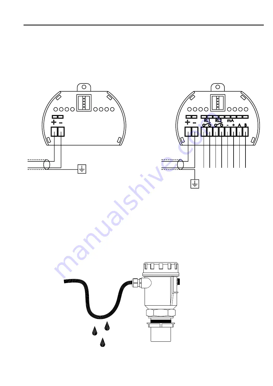
electrical connections
No
c
No
c
-
+
A
B
RL1
RL2
4÷20mA
MUDBUS
ALIM. 24Vdc
4÷20mA (24Vdc)
HART (opz.)
2 - WIRE VERSION
4 - WIRE VERSION
6-ELECTRICAL CONNECTIONS
6.1 WIRING
1) Separate the engine control cables or power cables from the METER connection cables
2) Open the cap by unscrewing.
3) Lead the cables into the transmitter through the glands
4) Do not use sleeves terminals, because they might interfere with the VL601 module insertion
5) Close the cap and tighten the cable glands
6.2 HUMIDITY INFILTRATIONS
To avoid the humidity infi ltration inside the housing is recommended:
- for electrical connections, use a cable with a 6÷12mm outer diameter and fully tighten the M20 cable gland
- fully tighten the cap
- position the cable so that it forms a downward curve at the M20 output; in this way the condensation and/or rain
water will tend to drip from the curve bottom


