background image

GB


SGM Technology for Lighting


Synthesis Wash 700 

User’s Manual 1.00 

- 17 - 

I

NSTALLING  

/

 REPLACING THE LAMP


ATTENTION!


This fixture is designed exclusively for use with Osram HTI 

700W/SE/75 lamps. NEVER USE ANY OTHER TYPES OF LAMPS. 


DISCONNECT THE POWER SUPPLY BEFORE CARRYING OUT ANY WORK ON THE FIXTURE. 


MAKE CERTAIN THAT THE FIXTURE IS OFF AND THE TEMPERATURE OF THE COMPONENTS 
CAN'T CAUSE BURNS (WAIT AT LEAST 30 MINUTES AFTER SWITCHING OFF). 


NEVER CARRY OUT ANY WORK IF THE FIXTURE DOESN'T HAVE ITS PROTECTIVE COVERS OR 
ITS LENSES ARE DAMAGED.DISCHARGE LAMPS CAN EXPLODE. 


NEVER LOOK DIRECTLY AT THE LAMP WHEN IT'S LIT - DISCHARGE LAMPS EMIT UV RAYS 
WHICH ARE DANGEROUS FOR SIGHT. 


Inside the fixture's moving head, there is an optical system. Follow the herebelow instructions when 
installing or replacing a lamp.


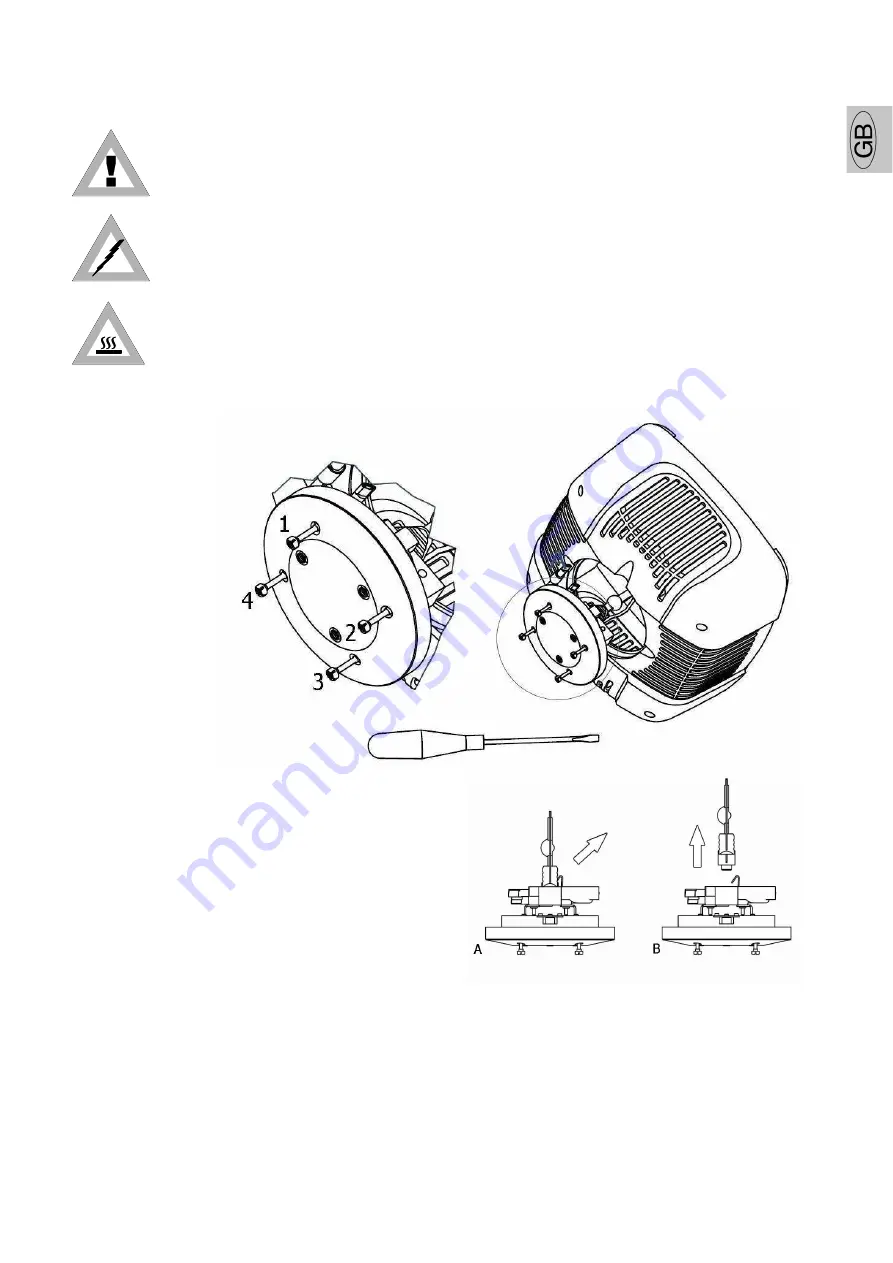
Fig. 3


1.


Through a screwdriver untighten the screws indicated in picture 1 with numbers 1.2.3.4. 

2.


Remove the rear cover where the socket is located, as indicated in picture 2. 

3.


Pull the lamp fixing spring as indicated in picture 3 and at the same time remove the lamp from 
the lamp holder as indicated in picture 3B. 

4.


Never touch the lamp bulb bare handed. Always use a cloth or gloves to handle the lamp during 
insertion or removal operations. 

Fig. 1 

Fig. 2 

www.audiovias.com

Summary of Contents for Synthesis Wash 700

Page 1: ...A L R E L 1 0 0 S G M T E C H N O L O G Y F O R L I G H T I N G S P A V I A P I O L A T O R R E 1 _ 6 1 0 1 0 T A V U L L I A P U I T A L Y T E L 3 9 0 7 2 1 4 7 6 4 7 7 _ F A X 3 9 0 7 2 1 4 7 6 1 7...

Page 2: ...beh lt sich das Recht vor Verbesserungen an den Produkten vorzunehmen und deshalb empfehlen wir die Bedienungsanleitung dem Produkt stets beizulegen und die Seriennummer auf der letzten Seite des Umsc...

Page 3: ...N A SUPPORT STRUCTURE 11 2 4 POSITIONING THE FIXTURE 11 2 5 FITTING CLAMPS 12 CONSTRUCTION OF THE SIGNAL CABLE 13 CABLES CONNECTIONS 13 CONSTRUCTION OF THE DMX TERMINATION 14 WIRELESS DMX 14 RDM REMOT...

Page 4: ...LIT MUST BE NO LESS THAN 1 5 METRES Changes to this manual SGM has an on going product development policy so the information printed in this manual may not be completely up to date If any doubts aris...

Page 5: ...PERSON NEVER USE THE FIXTURE UNDER THE FOLLOWING CONDITIONS IN PLACES SUBJECT TO EXCESSIVE HUMIDITY IN PLACES SUBJECT TO VIBRATIONS OR BUMPS IN PLACES WITH A TEMPERATURE OF OVER 45 C OR LESS THAN 2 C...

Page 6: ...on presentation of the guarantee certificate to the manufacturer or the nearest SGM technical assistance centre Always quote the unit s serial number and model when contacting your reseller for infor...

Page 7: ...ar Dimmer 0 100 12 flashes sec Strobe with music synchronism Color wheel with 4 positions white CMY system changeable colors CTO Colorchanger with music synchronism 16 speeds Rainbow On off Frost filt...

Page 8: ...ture life counter Software update via DMX CONTROL CHANNELS DMX 512 RS 232 input signal 20 DMX channels Wireless DMX interface as standard RDM protocol implemented on DMX internal parameters monitoring...

Page 9: ...he electrical installation making everything transparent to the end user The protections are 1 Protections against the overvoltage In case of power supply over 280 Vrms due to the neutral detachment t...

Page 10: ...an have this function as standard Lamp HTI 700W SE 7200 K HTI 700W SE 5600 k Luminous flux 59000 Lumen 59000 Lumen Color coordinates Y 332 X 345 Color temperature 7200 K 5600 K Luminous efficacy 85 lm...

Page 11: ...onato PESO 39 5 KG DIMENSIONI IN mm 1 3 5 M A X 1 3 5 M A X 530 SGM TECHNOLOGY FOR LIGHTING SI RISERVA IN QUALSIASI MOMENTO DI APPORTARE MIGLIORIE E MODIFICHE AI PROPRI PRODOTTI RIFERITE SEMPRE IL MAN...

Page 12: ...S FOAM NAILS ETC MUST NEVER BE LEFT NEAR CHILDREN AS DANGEROUS USE THE ORIGINAL PACKAGE IN CASE OF FIXTURE RETURN TO THE MANUFACTURER FOR REPAIR OR MAINTENANCE SERVICE IT HAS BEEN SPECIFICALLY MADE TO...

Page 13: ...ibrations or bumps In place subjet to temperatures of more than 45 or less than 2 C AVOID ANY KIND OF DIRECT CONTACT WITH THE LAMP DO NOT PLACE THE UNIT ON INFLAMMABLE PARTS OR MATERIAL PROTECT THE UN...

Page 14: ...n if the fixture is suspended from a truss suspended above ground or floor level fix the fixture with a steel safety cable Fix the fixture to the support structure using two safety chains fixed to the...

Page 15: ...NS see illustration taking care with the screen which must be connected to Pin 1 ATTENTION the screened parts of the cable sleeve must NEVER be connected to the system s earth as this would cause faul...

Page 16: ...WIRELESS on ON This will enable a new communication 3 Press the LOG key on the Transmitter to connect the receiver placed on the fixture to the wireless transmitter RDM REMOTE DEVICE MANAGEMENT RDM s...

Page 17: ...software version Please follow the below procedure to perform the updating 1 Install the USB DMX driver on the PC you will use to download the software The driver and the instructions to install it w...

Page 18: ...is switched off and that there is no risk of burns due to high component temperature wait at least 30 minutes after switching off To access internal components proceed as follows 1 Place the head of t...

Page 19: ...DISCHARGE LAMPS CAN EXPLODE NEVER LOOK DIRECTLY AT THE LAMP WHEN IT S LIT DISCHARGE LAMPS EMIT UV RAYS WHICH ARE DANGEROUS FOR SIGHT Inside the fixture s moving head there is an optical system Follow...

Page 20: ...witch it on 2 Connect the fixture to a lighting console 3 Point the fixture at a flat surface if possible white or light colored at least three metres from the fixture 4 Set the control channels to ob...

Page 21: ...the color wheel as indicated in picture A1 2 Grip the dichroic filter between your fingers and slide the filter out as indicated in picture A2 Installation of the new color filter 1 Carefully widen t...

Page 22: ...ed by an internal buffer battery which enables to use the display functions even by not powered fixture For powering the dispaly from the battery press the enter key for some seconds and the display w...

Page 23: ...he previous WIRELESS setting ON Enables the wireless signal output on the DMX OUT port WIRELESS EXIT OFF Disables the wireless signal output on the DMX OUT port 16 bit bitEnable the Pan Tilt movement...

Page 24: ...rol board in in centigrade degrees PAN F Shows the temperature of the the pan Control board in Fahrenheit degrees TILT C Shows the temperature of the the tilt Control board in centigrade degrees TILT...

Page 25: ...ftware version GOBO 1 0 Shows the Processor gobo board software version ZOOM 1 0 Shows the Processor zoom board software version CMY 1 0 Shows the CMY board software version VERSION HEAD 1 0 Displays...

Page 26: ...81 5 077 6 101 6 096 7 121 7 115 8 141 8 134 9 161 9 153 10 181 10 172 11 201 11 191 12 221 12 210 13 241 13 229 14 261 14 248 15 281 15 267 16 301 16 286 17 321 17 305 18 341 18 324 19 361 19 343 20...

Page 27: ...eceive a command To modify Pan movement proceed as follows 1 Connect Synthesis to the power supply wait till it has completed reset operations 2 Use the UP DOWN keys to find the Tilt Move menu 3 Press...

Page 28: ...of hours the lamp is lit elapsed time This is necessary to know in advance when it s almost time of relamping lamp life is approximately 750 hours To see how many hours a lamp has been used proceed as...

Page 29: ...ions 2 Use the UP DOWN keys to find the Lamp Strike menu 3 Press ENTER to confirm The message on the display will start to flash 4 Use the DOWN key to reset the meter 5 On the contrary pressing the UP...

Page 30: ...on the fixture Wireless logoff This function allos to disable all the wireless communication previously activated To enable the LOGOFF proceed as follows 1 Connect Synthesis to the power supply wait t...

Page 31: ...nown with the names of TRAKING contol and VECTOR control and are determined by the presence of the Pan Tilt Speed channel In TRACKING mode the speed is determined by the cross fade time set on the con...

Page 32: ...as follows 1 Connect Synthesis to the power supply wait till it has completed reset operations 2 Use the UP DOWN keys to find the RESET CONTROL menu 3 Press ENTER to confirm The message on the displa...

Page 33: ...it till it has completed reset operations 2 Use the UP DOWN keys to find the DISPLAY FLIP menu 3 Press ENTER to confirm The message on the display will start to flash 4 Use the UP DOWN keys to select...

Page 34: ...display will show FACTORY OFF Restoring the default parameters This feature allows to reset the values of the parameters which were set immediately before FACTORY SET procedure In other words if the d...

Page 35: ...s keep pressed the enter key for 4 seconds to go out from the setting menu Test functions Test programs can be used in the event of it being necessary to check the correct operation of the fixture or...

Page 36: ...to the power supply wait till it has completed reset operations 2 Use the UP DOWN keys to find the TEMPERATURE menu 3 Press Enter to confirm 4 Use UP DOWN keys to select the temperature to be checked...

Page 37: ...ed receiving data failure CMY COM ERROR The Processor in receive data by the CMY processor board but the communication is disturbed receiving data failure HEAD COM ERROR The Processor in receive data...

Page 38: ...mponents You should clean the fixture on a regular basis In accordance with the environment in which it is installed the unit needs a different maintenance service as dust dirt smoke either cigarettes...

Page 39: ...NS AIR PASSAGE The fans shouldn t be obstructed by the dust Use a vacuum to remove the dirt from the head and base fans BUFFER BATTERY REPLACEMENT Synthesis battery is located in the base of the fixtu...

Page 40: ...ow music change See the table Ch7 Ch7 Frost Linear Frost See the table Ch8 Ch8 Shutter Strobe Shutter and strobe with music sync Black out gobo and colour change See the table Ch9 Ch9 Dimmer Mechanica...

Page 41: ...at speed 2 129 135 132 Rainbow at speed 3 136 142 139 Rainbow at speed 4 143 149 146 Rainbow at speed 5 150 156 153 Rainbow at speed 6 157 163 160 Rainbow at speed 7 164 170 167 Rainbow at speed 8 171...

Page 42: ...trobe at the frequence of 6 Hz 88 95 92 Strobe at the frequence of 7 Hz 96 103 100 Strobe at the frequence of 8 Hz 104 111 108 Strobe at the frequence of 9 Hz 112 119 116 Strobe at the frequence of 10...

Page 43: ...Frost inserted Cyan Ch15 DMX VALUE FUNCTION 0 Open 0 255 Linear variation 0 100 255 Full color Magenta Ch16 DMX VALUE FUNCTION 0 Open 0 255 Linear variation 0 100 255 Full color Yellow Ch19 DMX VALUE...

Page 44: ...96 103 100 Macro12 104 111 108 Macro13 112 119 116 Macro14 120 127 124 Macro15 128 135 132 Macro16 136 143 140 Reserved to future use 144 151 148 Reserved to future use 152 159 156 Reserved to future...

Page 45: ...ow ramp closing on the iris rapid opening Iris 8 Iris rapid closing and opening Iris 9 Odd Fixtures perform slow ramp opening on the iris even fixtures perform slow ramp closing on the dimmer Iris 10...

Page 46: ...9 119 153 47 217 7 26 206 90 117 154 46 218 7 27 205 91 116 155 45 219 7 28 203 92 115 156 45 220 6 29 202 93 114 157 44 221 6 30 200 94 112 158 43 222 6 31 199 95 111 159 42 223 6 32 197 96 110 160 4...

Page 47: ...www audiovias com...

Page 48: ...A L R E L 1 0 0 S G M T E C H N O L O G Y F O R L I G H T I N G S P A V I A P I O L A T O R R E 1 _ 6 1 0 1 0 T A V U L L I A P U I T A L Y T E L 3 9 0 7 2 1 4 7 6 4 7 7 _ F A X 3 9 0 7 2 1 4 7 6 1 7...

Reviews: