background image

TVC-TRF-10-AAT

29

© SGS electronic 2006-2021

6

changing sound and software

The module is delivered with sound and software. So changing sound and
software is optional.

You can find the files at this location on our website:

https://www.sgs-electronic.de/downloads/Full+Modul/TVC-TRF

To change sound or software, you need a µSD card and basic knowledge

how to copy files with your pc.

6.1

Changing the sound

You can use the sound files provides on our web site. If you want to change

the sound or create your own sound files, you need our FMC software. It is
provided for free, on our website.

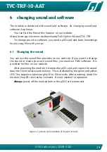
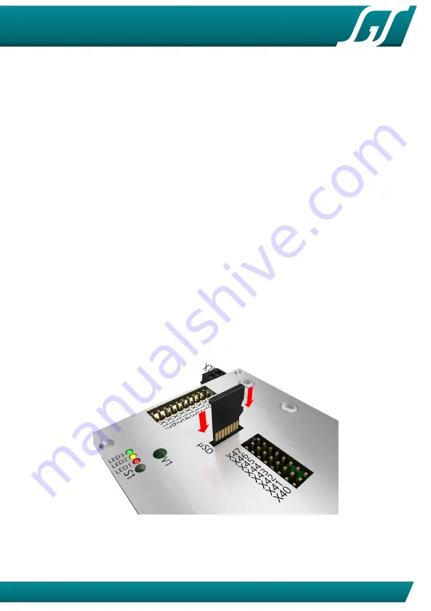
After powering the module, it detects the µSD card and copies the sound

data into the internal sound memory. This is indicated by the green and yellow
LED. This sequence takes roughly 30 to 60 seconds. After powering down the
module, the µSD card can be removed. It is not needed for operation.

Always

power off the module before the µSD Card is removed .

Figure 11: position and orientation of the µSD card slot

Summary of Contents for TVC-TRF-10-AAT

Page 1: ... AAT Full option module with sound for RC battle tanks in 1 16th to1 25th scale This module was developed to enable complete control of Gepard Flak panzer It can also control other modern air defense tracked vehicles such as Roland or the Tunguskta USSR ...

Page 2: ...ect the wiring Inexperienced modelers and persons under 16 should seek the assistance of an experienced modeler Always switch off power when working on the wiring Especial take care when connecting more than one receiver energy source Prevent the device from getting wet Check loads before connecting them to the modul at a current limited or fuse protected source ...

Page 3: ... 3 1 1 channel 1 12 3 1 2 channel 2 12 3 1 3 channel 3 12 3 1 4 channel 4 13 3 1 5 channel 5 13 3 1 6 channel 6 13 3 1 7 Channel 7 turn model off change model 14 3 1 8 Channel 8 Controlling the volume 14 3 2 Function of the light mode control 15 3 2 1 Tip 16 3 3 Automatic functions 16 3 3 1 35mm canon 16 3 3 2 MG 16 3 3 3 search radar 16 3 3 4 automatic engine stop 16 3 4 drive dynamic functions 1...

Page 4: ...4 X20 X21 23 4 5 connection of drive motors 23 4 6 connection of the switch outputs X08 to X17 25 4 6 1 Connection of lighting and exhaust systems 25 4 7 Connecting the speaker X70 26 5 Initialization 28 5 1 turn on sequence 28 5 2 operation modes 28 6 changing sound and software 29 6 1 Changing the sound 29 6 2 Changing the software 30 7 Practical tips 31 7 1 Neutral position 31 7 2 Failsafe rece...

Page 5: ...o output cables 21 8 motor connectors 24 9 switch outputs 25 10 speaker connector 26 11 position and orientation of the µSD card slot 29 12 rotating flasher wiring 32 13 LED resistor 33 14 resistor for LED groups 33 List of Tables 1 Overview control channels abbrevations refer to table 6 on page 34 14 2 light mode 15 3 motor and servo outputs overview 22 4 Allocation of terminal posts for the ligh...

Page 6: ...ction machines dumper trucks hydraulic excavators rope excavators dozers tanks main battle tanks mbt pso recovery tanks anti aircraft tanks armored person carrier excavator tanks amphibious tanks snow forming tracked vehicles tugs 2 1 FO modul features 6 integrated ESC with a drive capability of 2x10A and 4x3A clocked with 16kHz audio subsystem with 15W amplifier volume can be controlled by a trim...

Page 7: ...nnected soldered on the load side servo leads for receiver connection green connector for power supply X60 black connector for speaker X70 black connectors for X01 to X04 X20 and X21 2 4 accessories Connecting cables for outputs X08 to X17 light smoke generator etc are NOT included in the delivery These outputs can be used with standard three pin servo leads We offer different contacting options f...

Page 8: ...ircraft tanks turn the turret much faster than e g battle tanks Therefore and because there are much more wires the wiring between turret and hull is challenging To reduce the wire count the modul TVC TC13 can be used All control signals from the FO modul in the hull to the turret are concentrated on the SCALEBUS This reduces the wire count from 15 to only 4 This lines can be feed using a rotary f...

Page 9: ... RC planes Control elements are often not all intended to directly output their switching state Their primary task in flight radios is to manipulate the function parameters of the mixers built into the transmitter The failsafe function if available should be set to output the mid position of all chanels The transmitter should not be set on the FO module The servo travel in dicator on the transmitt...

Page 10: ...onic 2006 2021 mid right As the switch don t move if you let him go the servo will not move also 4 using a three stage momentary switch a servo can also the moved to three positions mut it returns to mid after releasing the switch ...

Page 11: ... in three control modes that can be switched any time using one channel on your RC Using control mode 1 and 2 one stick is to control the tracks and one stick is to control the semi automatic Gun and tracking radar When using control mode 3 one stick is to control the tracking radar independent of the turret using the second stick The control mode is switched by a rc channel If this channel is unc...

Page 12: ...rotation proportional left right 3 1 2 channel 2 mode 1 and 2 Proportional forward reverse This channel also provides the information for brake and reverse lights and smoke generator mode 3 barrel elevation proportional up down 3 1 3 channel 3 Bei schneller Betätigung in die Maximalposition wird das MG oberer Anschlag bzw die Hauptwaffe unterer Anschlag ausgelöst Für das MG flackert eine Lampe LED...

Page 13: ... the turret directly Please note that this is possible only with servo output the gear motor output operates proportional to stick deflection speed control mode 3 identical to control mode 1 and 2 but the turret rotation is controlled separately 3 1 5 channel 5 Controlling the light mode Using this channel the rotating flasher the flasher can be controlled In addition there are two lamp outputs th...

Page 14: ...To do this you need receivers with the same channel crystals When using 2 4GHz receivers they must be bound to the same transmitter Using this channel is optional 3 1 8 Channel 8 Controlling the volume If this channel is connected to a receiver volume is controlled using this RC channel Otherwise the volume is controlled with Trimmer P1 chan nel plug op tional ra dio 1 2 3 1 X50 no StickS steering...

Page 15: ... off off off auto off blinker left and right auto left right warning flasher auto left right off auto left right rotating light 1 2 3 4 off on rotat ing on rotat ing off on rotat ing light off off on off off combat light off off off on off Table 2 light mode The lightmode is changed by tipping the stick The mode is count up road traffic 1 road traffic 2 road traffic 3 combat target practice road t...

Page 16: ...he expose sequence is triggered the search radar is deployed from its stowed position 1 second later the rotation motor is turned on As soon as it is commanded to return to the stowed position Stowage requires a switch to locate the correct position for the stowage sequence to commence When radar is stopped in position the controller waits 1 seconds and stows away 3 3 4 automatic engine stop In ca...

Page 17: ...ives a valid radio signal The outputs for the blowers and pump are operated as a function of acceleration and speed At idle the smoke is inactive As the model accelerates smoke increases proportional to setting and duration of the throttle During steady throttle travel the output is reduced by 50 by means of PWM 3 4 2 Reverse light The reverse light output is linked to channel 2 and is automatic A...

Page 18: ...TVC TRF 10 AAT 18 SGS electronic 2006 2021 3 4 5 Brake light The brake light is automatic Lights go out automatically with resumed throttle ...

Page 19: ...operation of each function is given by the modul While lights blinker and motors can easily be assigned by wiring it is not that easy for servos In addition the servos parking positions are given by the modul Before mounting any servo into the model chech the function on your desktop and check carfully the operation direction for channel 1 steering tracked drive directions blinker left right turre...

Page 20: ... Fahrakku minus Figure 3 battery cable shown with polarity 4 2 connection to the receiver X50 to X511 The connection to the receiver is made using jr patch cables One side is plugged into the module and one side is connected to the receiver picture 5 shows how the connectors are plugged into the module The ground black or brown line of the servo cable is closest to to the bottom of the module Most...

Page 21: ...nto damage if one of the BEC units is a switching voltage regulator SBEC In this case pull the 5V red cable from all servo cables and isolate them with a tape or shrink wrap 4 3 connection of the servo outputs X40 to X47 The servos that are controlled by the module are connected to the connectors X40 to X47 Picture 7 shows the orientation of the connector The ground black or brown line of the serv...

Page 22: ...o a motor output behave like a gear motor Stick deflection results in rotation in proportion to motion Release the stick and the servo stops without returning to zero position For that reason only servos must be plugged in to this chanels ESCs plugges to this channels will not stop when returning to neutral as most one would expect 4 3 1 Connect the turret and cannon elevation motor servos The tur...

Page 23: ...led We suggest using a sail winch servo with 180º travel way This makes building a transmission easier 4 3 3 Connection of search radar elevation servo The search radar elevator servo must be connected to X44 The range of the search radar elevation servo is 45º The stowed position is 45º 4 3 4 Connection of the park position sensor The park position sensor must be connected to X511 The sensor must...

Page 24: ...TVC TRF 10 AAT 24 SGS electronic 2006 2021 Figure 8 motor connectors Tip Connect the blinker brake and reverse light to not confuse the polarity of the Motors ...

Page 25: ...re switched to ground The common connector is connected to battery Tip The left connection permanent is the same for all eight connectors To reduce lead count you can use one for several loads 4 6 1 Connection of lighting and exhaust systems This outputs switch the battery voltage so the connected load must be able to stand the voltage Example If the model is operated with a 12V battery the connec...

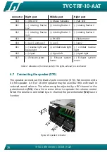
Page 26: ... signal left signal right X17 Exhaust system Exhaust system heater Exhaust system motor Table 4 Allocation of terminal posts for the lights exhaust fan and heater 4 7 Connecting the speaker X70 The speaker connects at the black 2 pole connector X70 We recommend a 4 ohm speaker An 8 or 16 ohm speaker may be used but this will result in reduced sound volume The volume may be adjusted by a RC channel...

Page 27: ...he presence of a box also improves bass response and sound volume The box should have as much volume as practical and should not hinder airflow from the face of the speaker Tip 2 In case you want to connect an external audio amplifier you need an amplifier with an speaker input or you have to connect an audio transformer ...

Page 28: ...is repeated at every start The start position of the controls are set as center This applies to all channels When doing the calibration the optional channels can be left unconnected In this case the module detects the channels to be unused You can not connect an optional channel after the calibration finished Case one of the not optional channels leaves unconnected the calibration will not end and...

Page 29: ...g the sound You can use the sound files provides on our web site If you want to change the sound or create your own sound files you need our FMC software It is provided for free on our website After powering the module it detects the µSD card and copies the sound data into the internal sound memory This is indicated by the green and yellow LED This sequence takes roughly 30 to 60 seconds After pow...

Page 30: ...ded 6 flashes program file crc error starts previous image if loaded Table 5 boot loader error codes 6 2 Changing the software The module is equipped with a so called bootloader After powering the module it checks if a µSD card is plugged and a valid software is stored on the card To update or change the kind of model Battletank Recoverytank Anti Aircraft Tank Armored person carrier two files have...

Page 31: ...of the channels every time you turn on power If you use a failsafe receiver please adjust it to deliver the same signals that are delivered when the sticks are in neutral position Or turn off the failsafe function Otherwise the module calibrates the wrong neutral positions 7 3 Do not use provisionally methods of connectivity Solder or screw all the electrical connections Provisionally connections ...

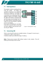
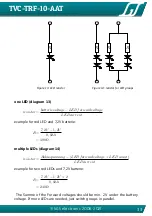
Page 32: ...r 12V 6V Lamps can be connected using re sistors or 5 6V Zener diodes to operate them at 12V supply If you want to connect your own elec tronic this can be done by connecting all minus outputs and use them as mi nus for your flasher X10 X11 X12 X13 X14 X15 X16 X17 Figure 12 rotating flasher wiring 7 6 Connecting LED When connecting LED please use suitable resistors On page 33 correct way to calcul...

Page 33: ...oltage LEDcurrent example for red LED and 7 2V batterie R 7 2V 1 2V 0 02A 300Ω multiple LEDs diagram 14 resistor Akkuspannung LEDforwardvoltage LED count LEDcurrent example for two red LEDs and 7 2V batterie R 7 2V 1 2V 2 0 02A 240Ω The Summe of the Forward voltages should be min 2V under the battery voltage If more LEDs are needed just switch groups in parallel ...

Page 34: ...iring compared to a classic bulb it has a polarity and a resistor is needed to limit the current Scalebus The Scalebus is a development of SGS electronic to connect con trollers and modules to compose solutions for complex RC models SBus The Sbus has been introduced by Futaba to simplify the wiring between RC Receivers and servos esc Ab bre va tion meaning explanation Stick Stick Stick not self ce...

Page 35: ...ltage drop in motor stage 0 3 Volt rated current X08 to X17 0 4 amp per chanel rated power audio amplifier 8W 7V 14W 12V supply voltage 7 2V bis 16V equals 12V pb battery max 11 pb cells max 12 NiCd NiMh cells max 4S Lipo rated current BEC servo outputs 1000mA rated current BEC receiver output 800mA maximum power disapation 5 Watt maximum operation temperature 75 C diemnsions without connectors 65...

Page 36: ...ltage or reverse the battery polarity Do not use in a careless or abusive fashion around persons or property Do not attempt to repair Any legitimate use e g Installation in a model makes the user responsible to ensure that the operating instructions and non liability agreement are provided to the purchaser of the module described above Do operate the device only in the permissible operating condit...

Reviews: