background image

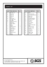
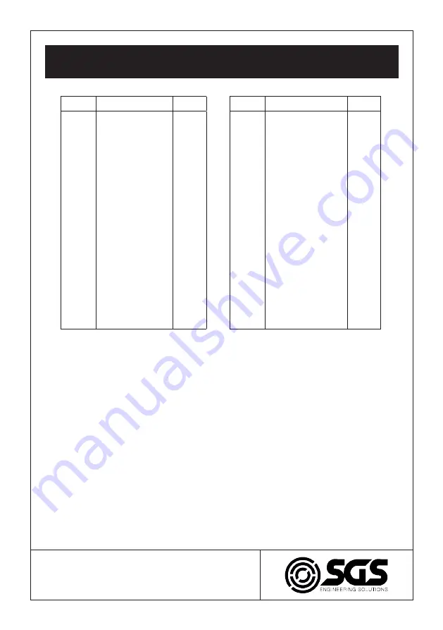
PARTS LIST

PART

DESCRIPTION

QTY

01
02
03
04
05
06
07
08
09
10
11
12
13
14
15
16
17
18
19
20
21

Screw nut
O-ring
Spring
O-ring
Bolt
Air inlet
Trigger bolt
Trigger
Main housing
Bearing
Rear plate
Bolt
Rotor
Rotor blade
Cylinder
Front plate
Bearing
Spacer
Gear sleeve
Nut
Gear

1
1
1
1
1
1
1
1
1
1
1
1
1
4
1
1
1
1
1
1
3

PART

DESCRIPTION

QTY

22
23
24
25
26
27
28
29
30
31
32
33
34
35
36
37
38
39
40
41

Bolt
Gear bracket
Lubricating sleeve
Bias axle
Bearing
Guiding sleeve
Ratchet holder
F/R stem
Spring
Top sleeve
Spacer
Ratchet bracket
Bolt
Ratchet claw
D-type head
Spring
Steel ball
Cushion
Block ring
Soft grip

3
1
1
1
1
1
1
1
1
1
1
1
1
1
1
2
2
1
1
1

FOR YOUR SAFETY
PLEASE READ THESE INSTRUCTIONS CAREFULLY
AND RETAIN THEM FOR FUTURE USE.

Summary of Contents for SAT105

Page 1: ...FOR YOUR SAFETY PLEASE READ THESE INSTRUCTIONS CAREFULLY AND RETAIN THEM FOR FUTURE USE OWNER S MANUAL SAT105 RATCHET WRENCH ...

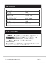
Page 2: ...SAFETY GUIDELINES Please read and fully understand the manual for information relating to protecting YOUR SAFETY and PREVENTING EQUIPMENT PROBLEMS Indicates an immediately hazardous situation which if not avoided will result in death or serious injury DANGER WARNING NOTE Indicates a potentially hazardous situation which if not avoided could result in death or serious injury Alerts the operator to ...

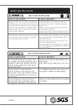
Page 3: ...d RISK OF FIRE OR EXPLOSION WHAT COULD HAPPEN HOW TO PREVENT IT Abrasive tools such as sanders and grinders rotating tools such as drills and impact tools such as nailers staplers wrenches hammers and reciprocating saws are capable of gen erating sparks which could result in ignition of flammable materials Never operate tools near flammable sub stances such as petrol naphtha cleaning solvents etc ...

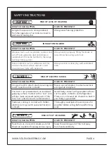
Page 4: ...EVENT IT Using air tools to attach electrical wiring can result in electrocution or death Never use nail staplers to attach electrical wiring while energized This tool is not provided with an insulated gripping surface Contact with a live wire will also make exposed metal parts of the tool live and can result in electrocution Avoid body contact with grounded surfaces such as pipes radiators and re...

Page 5: ...ve air hose to lubricate or add grind ing attachments sanding discs drills etc to the tool Never carry the tool by the hose Avoid unintentional starting Don t carry the tool with a finger on the trigger Only an authorised service representative should perform repair servicing Air tools can cause the work piece to move upon contact leading to injury Use clamps or other devices to prevent movement L...

Page 6: ... of mov ing parts breakage of parts and any other condition that affects the tool s operation If damaged have the tool serviced and repaired before use Use only accessories identified by SGS Engineering as suitable for use with specific tools Use of an accessory not intended for a specific tool increases the risk of injury to persons WARNING RISK OF ENTANGLEMENT WHAT COULD HAPPEN HOW TO PREVENT IT...

Page 7: ...an the air inlet filter cartridge weekly The recommended hook up procedure can be viewed in the diagram below 6 Line pressure should be increased accordingly to make up for extra long air hoses usually over 8 metres The minimum hose diameter should be 1 4 I D and the fittings should have the same inside dimensions But usually a 3 8 I D air hose is recommended for air supply to get the best functio...

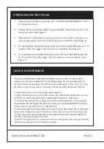
Page 8: ...and place 4 or 5 drops of air tool oil into the air inlet then re connect the air hose and run the tool to evenly distribute the oil throughout the tool for approximately 30 seconds This will prolong the tool life 5 Avoid storing the tool in a humid environment which promotes rusting of internal mechanisms Always oil the tool before storage OPERATING INSTRUCTIONS 1 Lubricate the tool before operat...

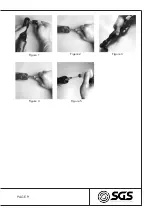
Page 9: ...PAGE 9 Figure 1 Figure 2 Figure 3 Figure 4 Figure 5 ...

Page 10: ...ns in this manual 3 Adjust the regulator on the tool to maximum setting Adjust the compressor regulator to tool maximum of 90 PSI 4 Tighten and seal hose fittings if leaks are found Use sealing tape 5 Be sure the hose is the proper size Long hose or tools using large volumes of air may require a hose with an I D of 1 2 in or larger depending on the total length of the hoses Do not use a multiple n...

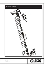
Page 11: ...PAGE 11 PARTS DIAGRAM N O P Q R S T U O T O R O N O M N V N U N T N S N R N Q N O N N N M O P O O O V PM P N PP P Q P R P T P U P S Q M P V P O O U O Q V O S Q N N P ...

Page 12: ...t Gear 1 1 1 1 1 1 1 1 1 1 1 1 1 4 1 1 1 1 1 1 3 PART DESCRIPTION QTY 22 23 24 25 26 27 28 29 30 31 32 33 34 35 36 37 38 39 40 41 Bolt Gear bracket Lubricating sleeve Bias axle Bearing Guiding sleeve Ratchet holder F R stem Spring Top sleeve Spacer Ratchet bracket Bolt Ratchet claw D type head Spring Steel ball Cushion Block ring Soft grip 3 1 1 1 1 1 1 1 1 1 1 1 1 1 1 2 2 1 1 1 FOR YOUR SAFETY PL...

Page 13: ...con forms to the above European Communities Directive s and Standard s PLACE DATE Signature Robert Wyatt Company Secretary Derby UK 24th JUNE 2017 SGS Engineering UK Ltd SGS Engineering UK Ltd West Side Park Raynesway Derby DE21 7AZ Ratchet Wrench SAT105K 2006 42 EC Machinery Directive EN1494 2000 Mobile or moveable jacks and associated lifting equipment APPLICATION OF EC COUNCIL DIRECTIVES STANDA...

Reviews: