PAGE 9
PAGE 8
CARE & MAINTENANCE
The tool should be lubricated daily (or before each use) with air tool oil (not in-
cluded). Air tool oil is available from SGS Engineering. Do not use detergent oil.
During continuous operation, the tool should be oiled every 1 to 2 hours. This may
be done using an in-line oiler or manually. If done manually, proceed as follows:
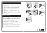
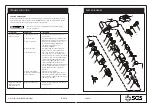
1. Disconnect the tool from air supply. (See Figure 6)
2. Place a few drops of air tool oil into the air inlet. (See Figure 7) Avoid the misuse
of thicker oil which may lead to the reduced performance or malfunction.
3. Connect the tool to the air supply. Run the tool without load for a few seconds
to distribute the oil through the tool. Any excess oil may be propelled from the air
exhaust area so point the tool in a safe direction.
4. After operating the tool and before storing the tool, disconnect the air hose and
place 4 or 5 drops of air tool oil into the air inlet, then re-connect the air hose and
run the tool to evenly distribute the oil throughout the tool for approximately 30
seconds. This will prolong the tool life.
5. Avoid storing the tool in a humid environment which promotes rusting of internal
mechanisms. Always oil the tool before storage.
OPERATING INSTRUCTIONS
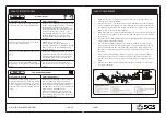
1. Lubricate the tool before operating. See “CARE AND MAINTENANCE” section
for oiling instructions.
2. Use the chuck key to open the chuck by screwing the key counterclockwise.
(See Figure 1)
3. Insert a drill or a drilling accessory (not provided) into the chuck and then
tighten the chuck by turning the key clockwise. Make sure that the drill/drilling
accessory is installed securely and tightened before operating the tool. (See
Figure 2)
4. Remove the air cap from the tool air inlet and mount the male plug. Connect
the air supply hose to the tool. Set the air pressure at 90 PSI. (See Figure 3)
5. Push F/R valve (Part #8) upwards (to “F” position) and press on the trigger to
operate the tool. (See Figure 4 & Figure 5)
6. Push F/R valve downwards (to “R” position) and press on the trigger whenever
you are releasing the drill out of the work piece. (See Figure 4 & Figure 5)
Figure 1
Figure 2
Figure 3
Figure 4
Figure 5
Figure 6
Figure 7
WWW.SGS-ENGINEERING.COM


