background image


17

  o

f


21


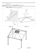
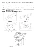
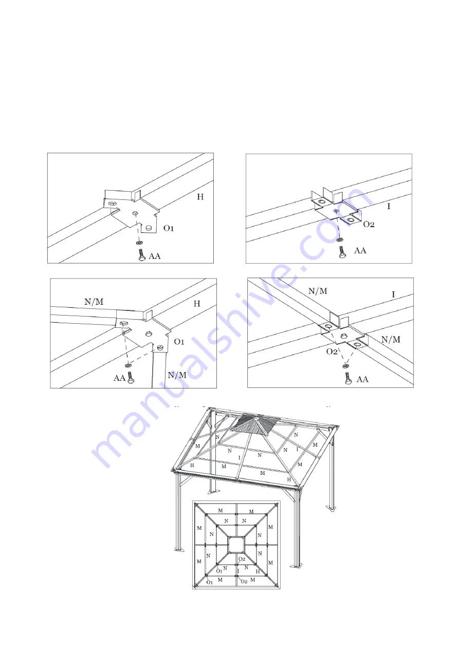
Step 11A:


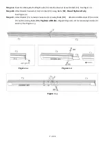
Attach the Main Roof Connectors (O1) to the Main Roof Corner Supports (H) using Bolts (AA). 
See Figure 11-1.


Step 11B:


Attach the Main Roof Connectors (O2) to the Main Roof Vertical Center Supports (I) using Bolts 
(AA). See Figure 11-2.


Step 11C:


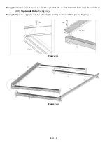
Attach the Main Roof Horizontal Supports (M and N) to the Main Roof Connectors (O1) using 
Bolts (AA). See Figure 11-3.


Step 11D:


Attach the Main Roof Horizontal Supports (M and N) to the Main Roof Connectors (O2) using 
Bolts (AA). See Figure 11-4.


Step 11E:


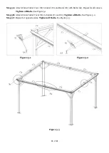
Repeat for all sides. 

Tighten all Bolts.

 See Figure 11-5.


Figure 11-1                                                                            Figure 11-2


Figure 11-3                                                                            Figure 11-4


Figure 11-5


Summary of Contents for 101642582

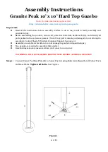
Page 1: ... of 21 Owner s Manual Granite Peak 10 x 10 Hard Top Gazebo Model Number GP GAZ10 2 SKU Number 101642582 Note This gazebo is designed to be used as a permanent fixture Scan For Video Assembly Instructions ...

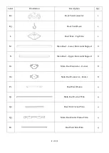
Page 2: ...Description Qty A Corner Post 4 B Corner Post Base Plate 4 C1 Lintel 4 C2 Lintel 4 E Lintel Corner Support Bar 8 F Lintel Bracket 4 G2 Lintel Connector 4 H Main Roof Corner Support 4 I Main Roof Vertical Center Support 4 J Main Roof Center Frame 1 K1 Roof Vent Corner Supports 4 ...

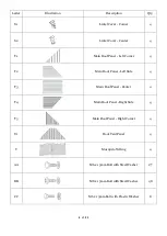
Page 3: ...oof Vent Top Trim 1 M Main Roof Lower Horizontal Support 8 N Main Roof Upper Horizontal Support 8 O1 Main Roof Connector Corner 8 O2 Main Roof Connector Center 8 P1 Roof Vent Frame 4 Q1 Main Roof Corner Trim 4 Q2 Roof Vent Corner Trim 4 Q3 Main Roof Center Frame Trim 4 R1 Roof Vent Side Trim 4 ...

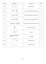
Page 4: ...f Panel Left Corner 4 T2 Main Roof Panel Left Side 4 T3 Main Roof Panel Center 4 T4 Main Roof Panel Right Side 4 T5 Main Roof Panel Right Corner 4 U1 Roof Vent Panel 4 V Mosquito Netting 4 AA M6 x 15mm Bolt with Steel Washer 177 BB M8 x 15mm Bolt with Steel Washer 48 CC M6 x 15mm Bolt with Plastic Washer 8 ...

Page 5: ...16 EE M6 x 25mm Bolt with Plastic Washer 24 FF M6 x 35mm Bolt with Plastic Washer 8 GG M6 x 40mm Bolt with Plastic Washer 8 II M6 x 55mm Bolt with Flat Washer Nut 4 JJ Mosquito Netting Hook 40 KK Spacer 24 LL Ground Stake 12 MM M8 Allen Wrench 1 NN M6 Hex Wrench 2 ...

Page 6: ... all parts packed in the carton are present Note If any part is missing or damaged do not attempt to assemble Contact Shade N Shelters Customer Support See page 21 Assemble on a stable level surface to avoid damage to gazebo and possible injury Two people are required to assemble this product Gazebo dimensions are measured from roof corner to roof corner WARNING DO NOT TIGHTEN BOLTS UNTIL NOTED AF...

Page 7: ...intel Connector G2 to Lintel C2 using Bolts BB Hand Tighten Only See Figure 2 2 Step 2C Attach Lintel C1 to Lintel Connector G2 using Bolts BB Attach Lintel Brackets F to Lintel C1 and C2 using Bolts BB Tighten all Bolts Repeat Step 2A to 2C for remaining Lintels C1 and C2 See Figure 2 3 Figure 2 1 Figure 2 2 Figure 2 3 ...

Page 8: ...ner Posts A to end of Long Lintels C1 and C2 first with Bolts AA then with Bolts DD Tighten all Bolts See Figure 3 1 Step 3B Repeat for opposite side Long Lintels C1 and C2 and Corner Posts A See Figure 3 2 Figure 3 1 Figure 3 2 ...

Page 9: ...with Bolts DD Repeat for opposite side Lintels C1 and C2 See Figure 4 1 Step 4B Attach Support Bars E to Lintels C1 and C2 and Corner Posts A with Bolts AA See Figure 4 2 Step 4C Repeat for all Corner Posts and Lintels Tighten all Bolts See Figure 4 3 Figure 4 1 Figure 4 2 Figure 4 3 ...

Page 10: ...tel C2 with Bolts AA Repeat for all corners Tighten all Bolts See Figure 5 1 Step 5B Attach Center Lintel Cover S2 to Lintels C1 and C2 Tighten all Bolts See Figure 5 2 Step 5C Repeat for opposite sides Tighten all Bolts See Figure 5 3 Figure 5 1 Figure 5 2 Figure 5 3 ...

Page 11: ... Main Roof Center Frame J and Corner Post A using Bolts AA See Figure 6 1 Step 6B Repeat for remaining Corners Tighten all Bolts Note Diagonal measurements from corner to corner must be within 5mm of the same distance See Figure 6 2 Figure 6 1 Figure 6 2 ...

Page 12: ... Main Roof Vertical Center Supports I to the Main Roof Center Frame J and the Lintel Brackets F using Bolts AA Hand Tighten Only See Figure 6 3 Step 6D Repeat for all sides Tighten all Bolts See Figure 6 4 Figure 6 3 Figure 6 4 J ...

Page 13: ... to Roof Vent Connector K2 with Bolts II See Figure 7 2 Step 7C Repeat for all corners See Figure 7 3 Step 7D Attach the sides of the Roof Vent Frame by connecting the Roof Vent Frame P1 to the Roof Vent Corner Support K1 using Bolts AA See Figure 7 4 Step 7E Repeat for all sides Tighten all Bolts See Figure 7 3 Figure 7 1 Figure 7 3 Figure 7 2 Figure 7 4 ...

Page 14: ...rame to the Main Roof Center Frame by inserting the Roof Vent Corner Supports K1 into the Main Roof Center Frame J and attach using Bolts AA See Figure 8 1 Step 8B Repeat for all corners Tighten all Bolts See Figure 8 2 Figure 8 1 Figure 8 2 ...

Page 15: ...P1 using Bolt CC See Figure 9 1 Step 9B Repeat for opposite sides Tighten all Bolts See Figure 9 2 Step 9C Attach the Roof Vent Trim R1 to the Sides of Roof Vent Frame P1 using Bolts AA Repeat for all sides Tighten all Bolts See Figure 9 3 Figure 9 1 Figure 9 3 Figure 9 2 ...

Page 16: ...pport K1 using Bolts FF See Figure 10 1 Step 10B Repeat for all corners Tighten all Bolts See Figure 10 2 Step 10C Attach the Roof Vent Top Trim L to the Roof Vent Center Support K2 using Bolt AA Tighten all Bolts See Figure 10 2 and Figure 10 3 Figure 10 1 Figure 10 3 Figure 10 2 ...

Page 17: ...orts I using Bolts AA See Figure 11 2 Step 11C Attach the Main Roof Horizontal Supports M and N to the Main Roof Connectors O1 using Bolts AA See Figure 11 3 Step 11D Attach the Main Roof Horizontal Supports M and N to the Main Roof Connectors O2 using Bolts AA See Figure 11 4 Step 11E Repeat for all sides Tighten all Bolts See Figure 11 5 Figure 11 1 Figure 11 2 Figure 11 3 Figure 11 4 Figure 11 ...

Page 18: ...ll bolts Step 12A Attach Main Roof Left Panel T1 to Lintel C1 using Bolt EE and Spacer KK Hand Tighten Only See Figure 12 1 Step 12B Attach Main Roof Left Panel T2 to Lintel C2 using Bolt EE and Spacer KK Note Panel T2 must overlap Panel T1 Repeat installation and overlapping for Main Roof Panels T3 T4 and T5 using Bolt EE and Spacer KK See Figure 12 2 Step 12C Repeat for opposite sides Tighten al...

Page 19: ... using Bolt GG Repeat for all corners See Figure 13 1 and Figure 13 3 Step 13B Attach the Main Roof Center Frame Trim Q3 to the Main Roof Center Frame J using Bolts AA Repeat for all sides Tighten all Bolts See Figure 13 2 and Figure 13 3 Figure 13 1 Figure 13 2 Figure 13 3 Figure 13 1 J ...

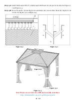
Page 20: ...ure 14 3 Step 14B Secure the gazebo by inserting the Ground Stakes LL into the Base Plates B Repeat for all corners See Figure 14 2 and Figure 14 3 Figure 14 1 Figure 14 2 Figure 14 3 Note Please see our video for additional assembly assistance https shadenshelters com 10x10 granite peak gazebo Figure 14 1 Figure 14 2 ...

Page 21: ...rposes damage due to acts of nature vandalism misuse or improper assembly are not covered Discoloration or fading of the finish or fabrics as a result of chemicals or spills pool water chemicals or salt water is not covered Mildew of fabric is not covered Corrosion and rusting of frames and hardware is not covered If within the stated warranty period this product is found to be defective in materi...

Reviews: