BK-T680 User’s Manual
8
3.3 Print module and controlling parts
The controlling parts include circuit board and the corresponding adjustment buttons, interfaces, etc.
3.3.1 Appearance of print module and controlling parts
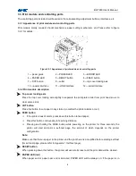
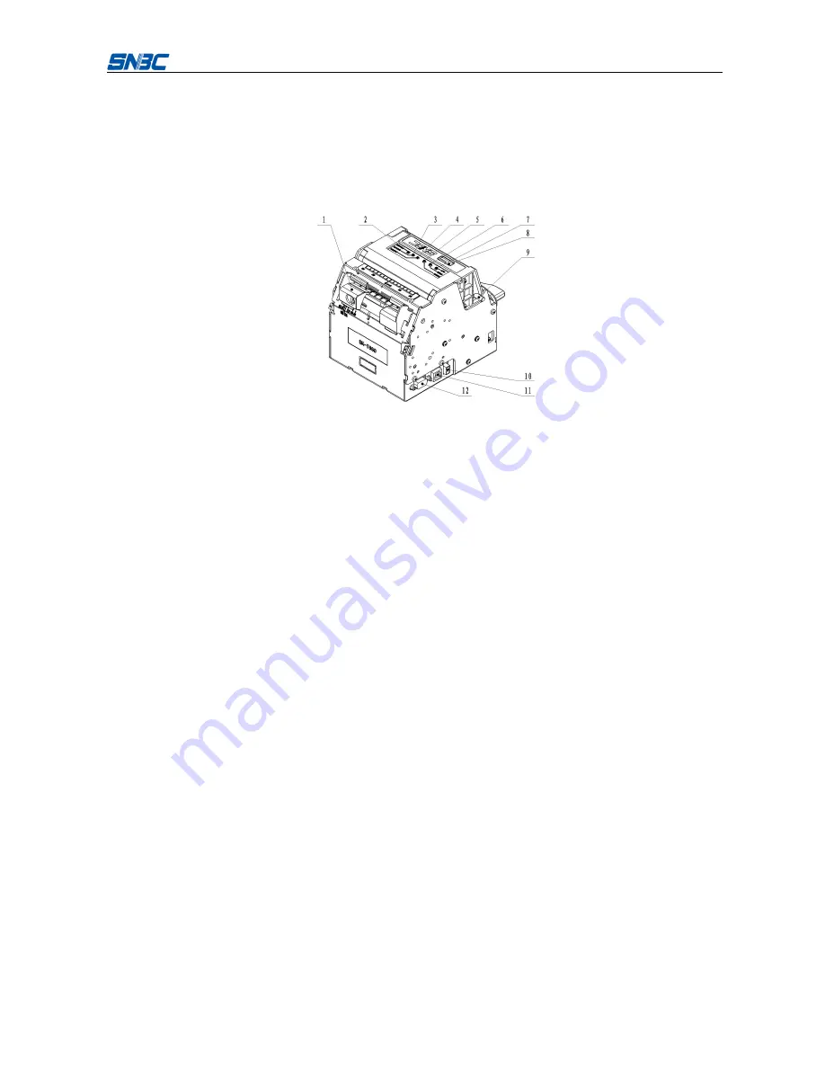
Print module mainly consists of print mechanism, paper cutting mechanism, etc. Please refer to figure
3.3-1 for details:
Figure 3.3-1 Appearance of print module and controlling parts
1 —paper guide
2 —POWER LED
3 —ERROR LED
4 —PAPER LED
5 —RESET button
6 —FEED button
7 —CUT button
8 —cutter
9 —top cover locking axis
10 —power interface
11 —USB interface
12 —serial interface
3.3.2 Print module description
Top cover locking axis
Press the top cover locking axis slightly to separate the print platen roller from print head so as to
clear some errors.
CUT button
Press this button to cut paper in any status (no matter the printer alarms or not).
FEED button
If the printer doesn’t alarm, press down this button to feed paper;
Press this button continuously to feed long distance;
Pressing and holding the FEED button while powering on the printer for three seconds, the
printer will start and print a self-test page, the printout of which depends on the printer
configuration.
Note:
Make sure that there is paper in the printer and the print head is not uplifted before starting self-test
(for self-test page, please refer to
Appendix 1 Self-test page
).
RESET button
When pressing down this button, the printer will execute its reset and the print data will be cleared.
PAPER LED (red)
When paper end or paper near end is detected, PAPER LED will be always on; If the paper is in

