background image

BK-T680 User’s Manual

12

4.4 Grounding

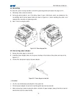
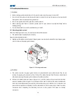
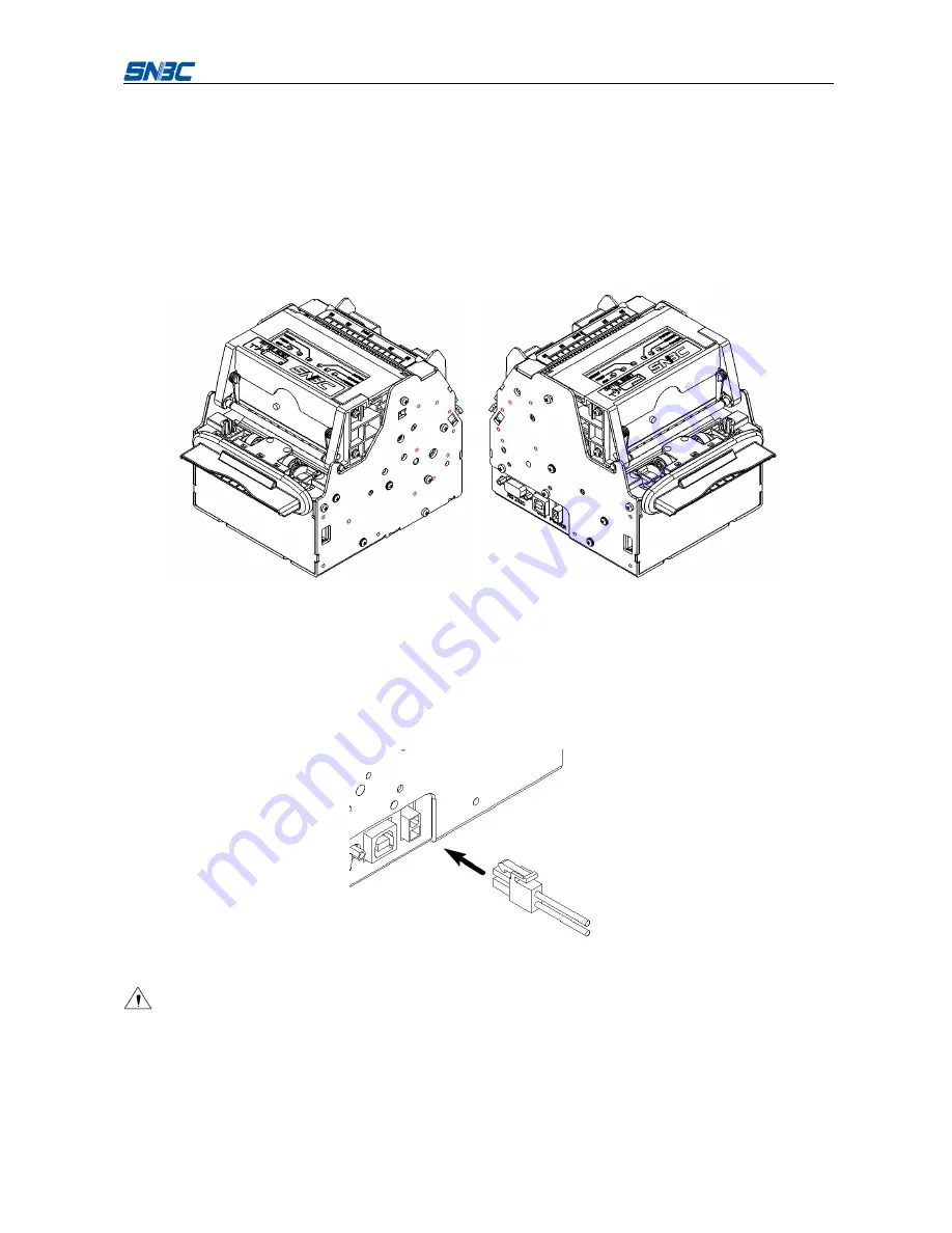
To ensure the printer is well grounded, connect the grounding cable as showed in the figure 4.3-1.

1)

Necessary tools: cross screw driver.

2)

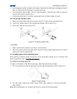
Fix the grounding cable to one of the fixing holes (14 pcs of M3 holes, which are installed on the

no-installing side of printer paper holder as shown in figure 4.4-1) when installing the printer, and

complete the connection of grounding cable.

3)

Note: The screw length is 4mm.

Figure 4.4-1 Grounding position

4.5 Connecting power adapter

1)

Ensure the printer power is turned off;

2)

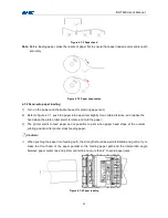
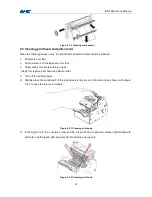
Insert the power adapter cable into the power interface at the bottom of the printer as shown in the

figure 4.5-1;

3)

Connect the input power supply of power adapter.

Figure 4.5-1 Connecting power adapter

Caution:

Use the recommended power adapter or its equivalents.

Connect power adapter connector at a right angle between pin and socket.

When connecting or disconnecting the cable connector of power adapter, always hold the connector

shell and don’t pull the cable forcibly.

Summary of Contents for BK-T680

Page 1: ...USER S MANUAL Embedded Printer BK T680 Shandong New Beiyang Information Technology Co Ltd...

Page 2: ...1 Trademark Registered trademark of SNBC Warning and caution Warning Items shall be strictly followed to avoid injury or damage to body and equipment Caution Items with important information and promp...

Page 3: ...unding outlet Avoid sharing one electrical outlet with large power motors or other devices that may cause the fluctuation of voltage 8 Disconnect the power when the printer is deemed to idle for a lon...

Page 4: ...10 4 2 Adjusting paper guide 10 4 3 Adjusting mark sensor position 11 4 4 Grounding 12 4 5 Connecting power adapter 12 4 6 Connecting interface cable 13 4 7 Installing paper roll and loading paper 13...

Page 5: ...6 2 USB interface 28 6 3 Power interface 29 7 Troubleshooting and maintenance 30 7 1 Error type and settlement 30 7 2 Solution for common errors 31 Appendix 33 Appendix 1 Self test page 33 Appendix 2...

Page 6: ...erial interface and USB interface Drivers are available for WINDOWS2000 XP 2003 Vista 2008 Win7 Windows XP Embedded operating systems and the software development kit based on DLL 1 2 Main features Pr...

Page 7: ...pside down print bold Barcode printing print barcode by commands in horizontal and vertical directions Character size Font A or Font B can be selected by commands Printer maintenance Replace paper rol...

Page 8: ...Image Barcode CODE128 ITF UPC A UPC E EAN13 EAN8 CODE39 CODE93 CODABAR PDF417 GS1 QR Character set Standard characters compressed characters Optional Asian character set simplified Chinese traditiona...

Page 9: ...2 2 Paper specifications Paper type continuous paper marked paper Paper supply mode paper roll Paper width 48 82 5 0 5 mm Paper thickness 55um 100um Thermal layer outward inward Paper roll specificati...

Page 10: ...ght can be set by adjusting the printer configuration Caution Please use the recommended paper or its equivalents Using other types of paper may affect print quality and even reduce the print head lif...

Page 11: ...arance Figure 3 1 1 BK T680 printer appearance 1 paper guide 2 button 3 print module 4 cutter 5 top cover locking axis 6 Presenter 7 LED paper outlet mouth 8 paper near end sensor socket 9 power inter...

Page 12: ...Figure 3 2 1 Overall size of printer with presenter Figure 3 2 2 Overall size of printer with presenter and anti jam module Note The overall size of the printer only with anti jam module is the same...

Page 13: ...arate the print platen roller from print head so as to clear some errors CUT button Press this button to cut paper in any status no matter the printer alarms or not FEED button If the printer doesn t...

Page 14: ...it is always on when the power is turned on Caution Print head The print head and motor generate heat in use please do not touch them just after operation 3 4 Presenter Figure 3 4 1 Presenter appeara...

Page 15: ...the paper guide to right position as showed in the following figure Three are six scale marks on bottom cover of paper guide 82 5mm 80mm 76mm 70mm 56mm 48mm Remove the paper guide to adjust the gap t...

Page 16: ...ure 4 3 1 and then rotate it in the direction shown by the green mark to adjust the position of mark sensor Figure 4 3 1 Adjusting mark sensor position 2 The bulge that aligns with scale mark indicate...

Page 17: ...able 3 Note The screw length is 4mm Figure 4 4 1 Grounding position 4 5 Connecting power adapter 1 Ensure the printer power is turned off 2 Insert the power adapter cable into the power interface at t...

Page 18: ...nterface cable Caution Make sure the interface cable is connected in correct direction When connecting or disconnecting the cable connector of power adapter always hold the connector shell and don t p...

Page 19: ...certain distance and release the hand when the platen roller starts to rotate and hold the paper 3 The printer starts to feed paper and is possible to print when paper head stops at the normal printin...

Page 20: ...notice 1 Install the printer on a flat and stable place Recommend installing horizontally the inclination angle shouldn t exceed 15 paper feeding direction Inclination in other directions should be no...

Page 21: ...th standard paper holder 2 Retraction space Space to collect the receipt not taken away by customer 3 PRESENTER space PRESENTER space is located inside the printer and its acceptable maximum length of...

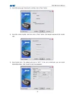
Page 22: ...nstallation 4 9 1 Typical installation Steps for typical installation are as follows 1 Run Setup_BK T680_EN V1 0 Setup exe Please read the legal agreement carefully If you agree to the terms of this a...

Page 23: ...pe Typical and then click on Next button 4 Select the current system and then click on Next button Not support windows 2000 in 64bit OS 5 Set printer port select port LPT1 as printer port and then cli...

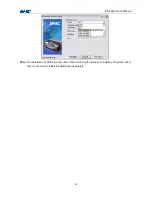
Page 24: ...n to set printer driving mode Steps for advanced installation are as follows 1 Run Setup_BK T680_EN V1 0 Setup exe Please read the legal agreement carefully If you agree to the terms of this agreement...

Page 25: ...click on Next button 4 Select the current system and then click on Next button Not support windows 2000 in 64bit OS 5 Select printer port The default print port is LPT1 If the port is USB port you can...

Page 26: ...BK T680 User s Manual 21 Note The installation of USB driver has been finished during the process of installing the printer driver thus do not need to install the USB driver separately...

Page 27: ...latches on both sides of paper guide cover and pull outward the top of paper guide cover to remove the paper guide module Figure 5 1 1 Cleaning mark sensor Caution The cable of sensor on paper guide m...

Page 28: ...ith big noises Steps for cleaning print head and platen roller 1 Turn off the printer power 2 Slightly press the central part of the locking axis of top cover in the direction as shown in the figure 5...

Page 29: ...t back to normal printing position after finishing printing PRESENTER can not hold paper normally Not execute paper retraction after PRESENTER holding paper Steps for cleaning paper out sensor 1 Turn...

Page 30: ...ates completely and turn on the power 5 5 Clearing jammed paper in the cutter When any of the following errors occurs please remove jammed paper manually Paper jams between platen roller and cutter Pa...

Page 31: ...is jammed into the path of presenter Paper does not enter paper out path of presenter Removing jammed paper in the following steps 1 Refer to step 3 in 5 3 Cleaning paper out sensor slightly press do...

Page 32: ...EPROM 6 1 2 Interface linking terminal distribution and signal function Printer signal and status is described as the following table No Signal name Signal direction Function 1 NC 2 TXD Output Data ou...

Page 33: ...nnector printer end USB B series socket Support and connect through USB HUB 6 2 2 Interface signal definition and functions Pin No Signal name Description 1 VBUS 5V 2 DATA Data transmission negative e...

Page 34: ...ce connector type molex 39 01 2020 Reference socket type molex 39 30 7025 Figure 6 3 1 Power socket and connector Pin definition of power interface Pin Signal definition Cable color 1 24V Red 2 GND Bl...

Page 35: ...end Automatic recovery after reloading paper Cutter error or paper jam Paper jams or cutter can t work normally Reloading paper after removing the jammed paper or press CUT button to cut paper Abnorm...

Page 36: ...s quality is poor Print head needs cleaning Print darkness is too low Input voltage is too low Make sure the paper roll is loaded correctly Use recommended paper or its equivalents Clean the print hea...

Page 37: ...on Connect the printer with the power correctly Turn on the printer The printer doesn t work after receiving commands Printer is in error status The communication cable is not connected well Interface...

Page 38: ...es Flash Logos Size 1536k Bytes Resolution 203 203DPI Print Width Max 80mm Fixed LeftMargin 2mm Fixed RightMargin 0mm PrintSpeed MAX 275mm s Dark Scale 100 Cutter Enabled Presenter Enabled Presenter M...

Page 39: ...66 1252 katakana More in Feed button configuration International Character U S A France German U K Denmart I Sweden Italy Spain Japan Norway Denmark II Spain II Latin America Bar Code Available UPC A...

Page 40: ...ng Flash Memory Size Printer FLASH capability Flash Logos Size Flash size for bitmap downloading Resolution Printer resolution Fixed LeftMargin Printer fixed left margin Fixed RightMargin Printer fixe...

Page 41: ...nted paper length Printer feed paper length total Tph Upside Print head parameter upside Printed lines Total Printer printed lines total Printed lines Actual Printer printed lines of current print hea...

Page 42: ...KDemo This tool is designed for KIOSK serial printers With it you can update the firmware of the printer edit and download logos edit and download code page print samples and so on KIOSKUtility This t...

Page 43: ...d paper near end sensor 10 Paper roll guide 11 Plastic paper roll shaft 12 Paper roll stopper 13 100mm cantilever paper holder Note Please adjust the mark sensor before installing cantilever holder Ap...

Page 44: ...BK T680 User s Manual 39 Figure appendix 3 1 2 Buffer rod installing direction Cantilever paper holder position Installation Buffer module installation 1 2...

Page 45: ...BK T680 User s Manual 40 3 4 5...

Page 46: ...BK T680 User s Manual 41 6 7 8 Note There are 9 positions for fixing between 100mm cantilever paper holder and printer mechanism which should be chosen according to the space needed...

Page 47: ...sert the plug of paper near end sensor into the socket of printer mechanism Appendix 3 1 3 Overall size of printer with cantilever paper holder The overall size of printer after assembling cantilever...

Page 48: ...Figure appendix 3 1 4 Installing 180mm cantilever paper holder on the left Figure appendix 3 1 5 Installing 100mm cantilever paper holder on the right Figure appendix 3 1 6 Installing 100mm cantilever...

Page 49: ...appendix 3 1 7 Adjusting paper guide of cantilever paper holder 2 Refer to the following figure the paper guide of cantilever paper holder can be adjusted to meet paper of width from 48mm to 82 5mm v...

Page 50: ...ameter of paper near end sensor is 29 5mm and the detecting paper roll diameter of weekend paper near end sensor is 40mm Level 2 The detecting paper roll diameter of paper near end sensor is 31mm and...

Page 51: ...aper near end 10m 11 6m 17 4m 26 2m 38 4m 100 Paper near end 2 3m 3m 5 3m 9 3m 15 1m Weekend paper near end 8m 9 3m 13 9m 20 9m 30 7m Table appendix 3 1 1 Minimum judge value of remaining paper Figure...

Page 52: ...igure unscrew the screw and adjust the paper guide of cantilever paper holder in the axial direction to adapt to 48 82 5mm width paper Figure appendix 3 1 13 Adjusting cantilever paper holder width Re...

Page 53: ...mum remaining paper detected by paper near end sensor is as follows theoretical value Paper thickness m Level 1 Level 2 Level 3 Level 4 65 6 3m 9 2m 16 2m 28 3m 80 5 1m 7 5m 13 1m 23m 100 4 1m 6m 10 5...

Page 54: ...BK T680 User s Manual 49 Refer to the following figure to replace the paper roll Figure appendix 3 1 16 Replacing paper roll...

Reviews: