background image

User’s guide


HRT/D   

-

11

HS 


Adjustment 


3.


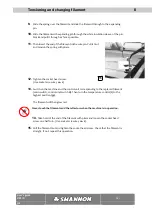
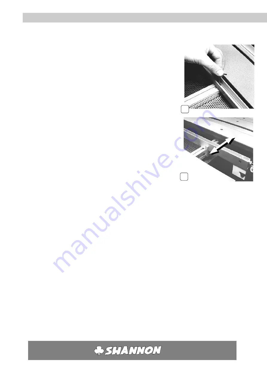
Loosen the socket head screw in the centre of the heating 
element one half turn.  
(Use socket screw key 

no. 3


4.


Take the heating element with both hands close to the supporting 
prongs on the left and right and slide it into the desired position. 
Hold the heating element parallel to the front of the machine and 
the supporting prongs. This prevents the notched nuts in the 
aluminium

 X

-profiles from binding. 


5.


Hand tighten the socket head screws, 

starting

 in the supporting 

prongs and 

then

 in the centre. 


6.


Position the other profiles in the same way if necessary. 


7.


Fill up the space between the heating elements as far as possible with solid core 
strips and hand tighten them. First slide the notched nuts into the aluminium 

X

-

profile roughly level with the holes and then lay the solid core strip on top. 


8.


Switch on the machine again as in Section 

5


Summary of Contents for HRT/D 300

Page 1: ...User s guide English Plastic Bending Machine HRT D...

Page 2: ...c bending machine HRT D 300 1995 SHANNON BV All rights reserved No part of this User s Guide may be photocopied altered or translated without prior written consent Information contained in this User s...

Page 3: ...8 5 4 Trouble shooting 8 5 5 Setting transport system 9 6 Adjustment 10 6 1 Safety measures 10 6 2 Lower heating element 10 6 3 Lower filament height 11 6 4Stop 12 7 Maintenance 13 7 1 Safety measures...

Page 4: ...ing and using the machine We want to keep in contact and to know how you find the HRT D We are always willing to advise on the use of the machine and its accessories SHANNON BV Turfschipper 11 13 2292...

Page 5: ...sport the work piece over the heating elements from the right to the left of the working surface This way all the sheets are equally heated and the full table length is in use The working surface is m...

Page 6: ...w R glage de vitesse Voltage 220 V Power 0 37 Kw Horsepower 1 500 R pm Mechanical gradation of stop max 1000 mm dimensions 3390x1300x1092 mm lxwxh weight 550 Kg life of filament Approx 600 hours Funct...

Page 7: ...is in operation Always wear close fitting clothing Be particularly careful of sleeves and always tie back long hair Never leave objects on the working surface The machine may only be used for heating...

Page 8: ...t if necessary 4 Ensure there is adequate ventilation and lighting at the workplace 5 Avoid draughts in order to prevent uneven heating When moving the machine with a forklift truck ensure that the ma...

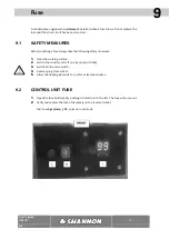
Page 9: ...e value up to 99 keeping this pressed in will make the value cycle much faster 3 Press the left button arrow down to decrease the value down to 00 keeping this pressed in will make the value cycle muc...

Page 10: ...the machine will operate the number of plastic sheets that are loaded b 8 The time in seconds that the pusher is reloading a new piece of plastic c 9 The time in seconds that the feeding system is pu...

Page 11: ...the working surface 3 Allow the heating elements to cool for at least 10 minutes 6 2 LOWER HEATING ELEMENT 1 Remove the strips of solid core material next to the heating element to be adjusted by loos...

Page 12: ...and the supporting prongs This prevents the notched nuts in the aluminium X profiles from binding 5 Hand tighten the socket head screws starting in the supporting prongs and then in the centre 6 Posit...

Page 13: ...is the same on both sides 2 Start up the machine again as in Section 5 6 4 STOP 1 Loosen both the handles on the stop one half turn 2 Slide the stop into the desired position Hold the guide parallel t...

Page 14: ...n a while 7 1 SAFETY PRECAUTIONS 1 Switch of all regulating units switch H 2 Clear the working surface 3 Remove the plug from the socket 7 2 PROFILES The heating elements work more effectively when th...

Page 15: ...l for at least 10 minutes 8 2 TENSIONING 1 Turn the filament to the lowest position 2 Hold the end of the wire on the right with pliers and undo screw in the wire pin Use socket screw key no 2 3 Pull...

Page 16: ...4 Slide the spring off the expanding pin 5 Unscrew the expanding pin from the connection screw incl connection wire 6 Remove filament from the expanding pin and the wire pin 7 Slide a new wire into th...

Page 17: ...the socket head screw Use socket screw key no 2 13 Switch on the machine and the control unit corresponding to the replaced filament main switch control unit switch H Then turn the temperature control...

Page 18: ...y measures 1 Clear the working surface 2 Switch the control units off one by one switch H 3 Switch off the main switch 4 Remove plug from socket 5 Allow the heating elements to cool for at least 10 mi...

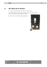
Page 19: ...move a number of solid core strips in the centre of the machine The circuit breaker which is at the front of the main switch box is now visible When the switch is down off the circuit breaker is switc...

Page 20: ...variety of widths and with 1 or 2 filaments Heating elements with 2 filaments are suitable for heating wide zones and for obtaining a large radius Maximum number of heating elements 4 Number of filame...

Page 21: ...3 2 mm Profile lengths 500 650 1000 en 1250 mm Ridge widths 1 to 10mm Number of ridge widths single and double Special versions on request Mould In which to allow the bent product to cool Adjustable t...

Page 22: ...eflectors with heating wire that is adjustable in height 2 upperreflectors pneumatic pressuresystem and stop all adjustable Easily extendable up to 8 regulating units with 4 under and 4 upperreflector...

Page 23: ...arranty on all parts with the exception of the filaments and or heating elements This warranty is inclusive of parts call out charge and labour The maximum replacement time for the control units is on...

Reviews: