14U10/15
14U20/25
6
6-1
6-2
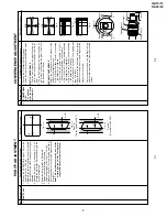
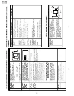
PIF ADJUSTMENT
No.
Adjusment point
Conditions/Adjusting pr
ocedure
W
a
vef
orm or other
s
T
uner IFT
( PRESET )
1
1.
Get the tuner ready to receiv
e the CH.
E - 9 sig-
nal, b
u
t with no signal input.
Adjust the PLL data.
2.
Connect the sweep generator's output cable to
the tuner antenna. ( RF SWEEP )
3.
Adjust the s
w
eep gener
ator's to 80dB
µ
V.
4.
Connect the response lead ( use LOW IMPED-
ANCE probe with wave detector ; see Fig.1 ) to
the tuner's IF output ter
minal.
(
This ter
minal must
ha
v
e
the probe alone connected ).
5.
Set the RF A
GC to 0 - 6
V with no satur
ation with
the waveform.
6.
Adjust the tuner IF coil to obtain the waveform as
shown in Fig. 2.
Note:
Be sure to keep the tuner cover in position
during this adjustment.
RF-AGC
T
AKE O
VER
POINT AD-
JUSTMENT
(I
2
C BUS
CONTROL)
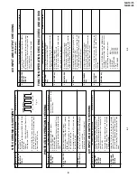
1.
Receiv
e
"P
AL COLOUR BAR" signal.
»
Signal Strength: 57
±
1 dB
µ
V (75 ohm open)
2.
Connect the oscilloscope to
TP201 (T
uner’
s
A
G
C
T
e
rm
inal) as sho
wn in Fig.
3.
3
.
Call "A
GC" mode in ser
vice mode
. Adjust the
"A
GC" b
us data to obtain the
T
uner output pin
drop 0.1V below maximum voltage.
4.
Change the antenna input signal to 63~67dB
µ
V,
and make sure there is no noise.
5.
T
u
rn
up the input signal to 90~95 dB
µ
V to be sure
that there is no cross modulation beat.
Note: For the 50 ohm signal
strength gauge, when not
using 50/75 impedance
adapter
, signal strength is
52
±
1dB
µ
V(75 ohm open), in-
stead of 57
±
1dB
µ
V (75 ohm
open).
Precaution: The loss of using
impedance adapter
2
»
Bias box:
About 4.5 V
Oscilloscope
0.1V
TV Set
Bias box
TP201
+
+
–
–
Fig. 3
E-9 CH
P
C
10k
100k
1n60
75ohm
IF OUT
-1.5+/-0.8dB
1000p
Oscilloscope
Fig.1
Fig.2
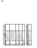
SHIPPING SETTING & CHECKING
(1)
The following default data has been factory-set for the E
2
PROM.
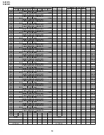
ITEMS
D
A
T
A
SETTING
LAST PROGRAM/CHANNEL
1
FLASHBACK PROGARM/CH
1
DIGIT
1
C-SYSTEM
A
U
T
O
S-SYSTEM
B/G
SKIP
OFF
AFC
ON
VOLUME
1
CONTRAST
60 (MAX)
COLOUR
0 (CENTER)
BRIGHTNESS
0 (CENTER)
TINT
0 (CENTER)
SHARPNESS
0 (CENTER)
WHITE TEMP
S
T
A
N
D
A
R
D
REMINDER TIMER
In-active,
"--:--"
ON TIMER
In-active,
"--:--"
OFF TIMER
In-active,
"--:--"
LAST POWER
POWER-ON
LANGUAGE
ENGLISH
BLUE BACK MUTE
OFF
HO
TEL MODE
OFF
Summary of Contents for 14U10
Page 22: ...14U10 15 14U20 25 22 MODEL 14U10 15 CHASSIS LAYOUT ...
Page 23: ...14U10 15 14U20 25 23 MODEL 14U20 25 CHASSIS LAYOUT ...
Page 24: ...14U10 15 14U20 25 14U10 15 14U20 25 24 25 BLOCK DIAGRAM 1 3 MODEL 14U10 15 MAIN BLOCK ...
Page 25: ...14U10 15 14U20 25 14U10 15 14U20 25 BLOCK DIAGRAM 2 3 MODEL 14U20 25 MAIN BLOCK 26 27 ...
Page 26: ...14U10 15 14U20 25 28 BLOCK DIAGRAM 3 3 MODEL 14U20 25 HEADPHONE BLOCK CRT BLOCK ...
Page 27: ...14U10 15 14U20 25 29 WAVEFORMS ...
Page 31: ...14U10 15 14U20 25 33 M E M O ...
Page 43: ...Ref No Part No Description Code Ref No Part No Description Code 49 14U10 15 14U20 25 ...


