background image

11

6

5

4

3

2

1

A

C

D

E

F

G

H

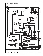
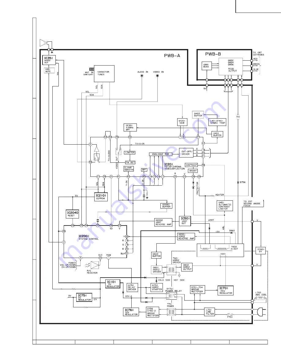
BLOCK DIAGRAM

20MU11

Summary of Contents for 20MU11

Page 1: ... for after sales service only The contents are subject to change without notice CONTENTS SERVICE MANUAL POWER INPUT 120 V AC 60 Hz POWER RATING 82 W PICTURE SIZE 1 194cm2 185sq inch CONVERGENCE Magnetic SWEEP DEFLECTION Magnetic FOCUS Hi Bi Potential Electrostatic INTERMEDIATE FREQUENCIES Picture IF Carrier Frequency 45 75 MHz Sound IF Carrier Frequency 41 25 MHz Color Sub Carrier Frequency 42 17 ...

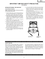
Page 2: ...meter should be checked periodically 3 High voltage should always be kept at the rated value no higher Operation at higher voltages may cause a failure of the picture tube or high voltage circuitry and also under certain conditions may produce radiation in exceeding of desirable levels 4 When the high voltage regulator is operating properly there is no possibility of an X radiation problem Every t...

Page 3: ... mechanical insulators and etc 3 To be sure that no shock hazard exists check for leakage current in the following manner Plug the AC cord directly into a 120 volt AC outlet Do not use an isolation transformer for this test Using two clip leads connect a 1 5k ohm 10 watt resistor paralleled by a 0 15mF capacitor in series with all exposed metal cabinet parts and a known earth ground such as electr...

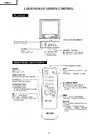
Page 4: ...4 LOCATION OF USER S CONTROL 20MU11 ...

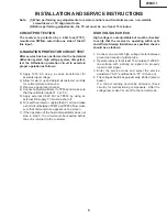
Page 5: ...f the horizontal oscillator does not stop in step 5 the circuit must be repaired before the set is returned to the customer HIGH VOLTAGE CHECK High voltage is not adjustable but must be checked to verify that the receiver is operating within safe and efficient design limitations as specified checks should be as follows 1 Connect an accurate high voltage meter between ground and anode of picture tu...

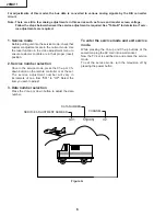
Page 6: ... Use the reset function in the video adjustment menu to ensure customer controls are in their proper reset position 2 Service number selection Once in the service mode press the Ch up or Ch down button on the remote controller or at the set The service adjustment number will vary in increments of one from S01 to OP Select the item you wish to adjust 3 Data number selection Press the Vol up or down...

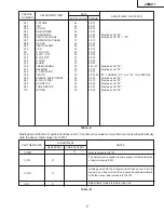
Page 7: ...03 No VERTICAL S20 ENERGY SAVE OFFSET 20 00 3F Must be set to 23 S21 D D E OFFSET 03 00 1F Must be set to 03 S22 OSD SETUP 00 00 03 Must be set to 00 S23 TUNER SETUP 00 00 01 Must be set to 00 OP OPTION 30 00 FF Must be set to 02 NECESSARY UNNECESSARY ADJUSTMENT NOTES PART REPLACED IC2001 IC2101 X CRT X IC201 X X Data is stored in IC2101 The adjustment is needed to compensate for characteristics o...

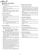
Page 8: ...aster screen cotrol until the raster darkens to the point where raster is barely seen 7 Adjust the service adjustments S11 red S12 green and S13 blue to obtain a good grey scale with normal whites at low brightness level 8 Select the service adjustment S19 and reset data to 00 Select the service adjustment S03 and reset data to obtain normal color level 9 Remove digital voltmeter and reset the mas...

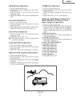
Page 9: ...rvice adjustment S18 3 A black text box appears on the screen see Figure B below 4 Adjust S18 data value so that text box is positioned in the center of the screen 3 58MHz Trap Adjustment 1 Receive a good local channel 2 Enter the service mode and select the service adjustment S16 3 This is a two position adjustment 00 is ON 01 is OFF 4 Adjust data value to 00 for normal viewing Sharpness Audio Ba...

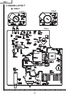
Page 10: ...10 6 5 4 3 2 1 A B C D E F G H CHASSIS LAYOUT Ë 20MU11 PWB B PWB A PWB B 20MU11 ...

Page 11: ...11 6 5 4 3 2 1 A B C D E F G H BLOCK DIAGRAM 20MU11 ...

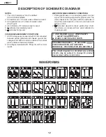
Page 12: ... All voltages measured with 1000µ V B W or Color signal WAVEFORM MEASUREMENT CONDITIONS 1 Photographs taken on a standard gated color bar signal the tint setting adjusted for proper color The wave shapes at the red green and blue cathodes of the picture tube depend on the tint color level and picture control 2 indicates waveform check points See chart waveforms are measured from point indicated to...

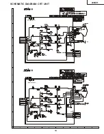
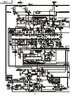
Page 13: ...6 5 4 3 2 1 A B C D E F G H 20MU11 SCHEMATIC DIAGRAM CRT UNIT DUNTK9533WEV4 DUNTK9530WEW6 13 ...

Page 14: ...14 20MU11 ...

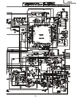
Page 15: ...15 20MU11 ...

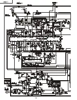
Page 16: ...16 20MU11 ...

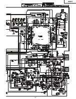
Page 17: ...20MU11 17 ...

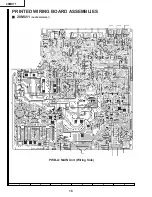
Page 18: ...18 6 5 4 3 2 1 A B C D E F G H PRINTED WIRING BOARD ASSEMBLIES Ë 20MU11 PWB A MAIN Unit Wiring Side 20MU11 DUNTK9529WEX7 ...

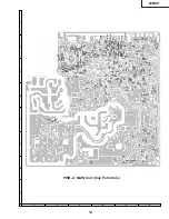
Page 19: ...19 6 5 4 3 2 1 A B C D E F G H PWB A MAIN Unit Chip Parts Side 20MU11 ...

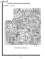
Page 20: ...20 6 5 4 3 2 1 A B C D E F G H Ë 20MU11 PWB A MAIN Unit Wiring Side 20MU11 PRINTED WIRING BOARD ASSEMBLIES DUNTK9532WEX0 ...

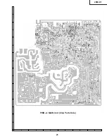
Page 21: ...21 6 5 4 3 2 1 A B C D E F G H PWB A MAIN Unit Chip Parts Side 20MU11 ...

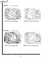
Page 22: ...5 4 3 2 1 A B C D E F G H PWB B CRT Unit Chip Parts Side PWB B CRT Unit Wiring Side PWB B CRT Unit Wiring Side PWB B CRT Unit Chip Parts Side Ë 20MU11 Ë 20MU11 20MU11 PWB B DUNTK9533WEV4 PWB B DUNTK9530WEW6 ...

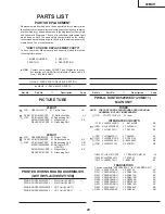
Page 23: ...Deflection Yoke AZ å L702 RCILG0099PEZZ M Degaussing Coil AM MSPRT0002MEZZ M Spring for CRT AA 20MU11 PMAGF3046CEZZ J Magnet Ass y AK QEARC2016PEZZ R Grounding Part PRINTED WIRING BOARD ASSEMBLIES NOT REPLACEMENT ITEM PWB A DUNTK9529WEX7 MAIN Unit 20MU11 PWB A DUNTK9532WEX0 MAIN Unit 20MU11 PWB B DUNTK9530WEW6 CRT Unit 20MU11 PWB B DUNTK9533WEV4 CRT Unit 20MU11 TUNER NOTE THE PARTS HERE SHOWN ARE ...

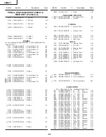
Page 24: ...FILC0446CEZZ J Ceramic Filter AE CF631 RFiLA0034CEZZ J Ceramic Filter AD CF2040 RFILA0099CEZZ J Ceramic Filter AD SF201 RFiLC0405CEZZ J SAW Filter AH COILS L201 VP XF1R2K0000 J Peaking 1 2µH AB L202 RCiLi0612CEZZ J VCO Coil AE L301 VP XF8R2K0000 J Peaking 8 2µH AB L302 RCiLi0613CEZZ J IF Coil AE L401 VP XF120K0000 J Peaking 12µH AB L402 VP XF100K0000 J Peaking 10µH AB L406 VP XF680K0000 J Peaking ...

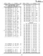
Page 25: ... C803 VCCCCY1HH120J J 12p 50V Ceramic AA C804 VCEA0A1HW104M J 0 1 50V EL AB C805 VCEA0A1HW104M J 0 1 50V EL AB C806 VCEA0A1HW104M J 0 1 50V EL AB C807 VCCCCY1HH820J J 82p 50V Ceramic AA C901 VCKYCY1EF104Z J 0 1 25V Ceramic AA C905 VCEA0A1HW335M J 3 3 50V EL AB C2001 VCCCCY1HH101J J 100p 50V Ceramic AA C2002 VCCCCY1HH101J J 100p 50V Ceramic AA C2021 VCCCCY1HH101J J 100p 50V Ceramic AA C2022 VCCCCY1...

Page 26: ...CY1JF152J J 1 5k 1 16W M Ox AA R633 VRS CY1JF472J J 4 7k 1 16W M Ox AA R634 VRD RM2HD121J J 120 1 2W Carbon AA å R641 VRS VV3AB682J J 6 8k 1W M Ox AA R642 VRD RA2BE821J J 820 1 8W Carbon AA çå R651 VRD RM2HD1R0J J 1 0 1 2W Carbon AA çå R654 VRD RA2BE154J J 150k 1 8W Carbon AA çå R655 VRS CY1JF104J J 100k 1 16W M Ox AA çå R656 VRS CY1JF273J J 27k 1 16W M Ox AA å R659 VRN VV3AB2R2J J 2 2 1W M Film A...

Page 27: ...5 QJAKE0211CE04 J Jack Video In AF P302 QPLGN0261CEZZ J Plug 2 pin S AB P401 QPLGN0561CEZZ J Plug 5 pin GBN AB P601 QPLGN0603CEZZ J Plug 6 pin K AB P651 QPLGN0361CEZZ J Plug 3 pin AB P701 QPLGN0260CEZZ J Plug 2 pin M AA P751 QPLGN0461CEZZ J Plug 4 pin YBN AB P2001 QPLGN0561CEZZ J Plug 5 pin AB RMC2601 RRMCU0230CEZZ J R C Receiver AK HM601 LX GZ3002PEZZ R Screw AB HM602 LX GZ3002PEZZ R Screw AB HM7...

Page 28: ...Diode 5 6V AB D455 VHD1SS119 1 J Diode AB D501 RH DX0441CEZZ J Diode AC PWB A DUNTK9532WEX0 20MU11 MAIN UNIT å D502 RH DX0131CEZZ J Diode AC D601 RH DX0441CEZZ J Diode AC D631 RH EX0630GEZZ J Zener Diode 9 1V AA D641 RH EX0630GEZZ J Zener Diode 9 1V AA çå D651 RH DX0131CEZZ J Diode AC çå D652 VHD1SS119 1 J Diode AB çå D653 RH EX0091CEZZ J Zener Diode 22V AB å D661 RH DX0444CEZZ J Diode AH å D701 R...

Page 29: ...2 VCEA0A1EW477M J 470 25V EL AD C504 VCKYPA2HB391K J 390p 500V Ceramic AA C505 VCQYTA1HM473K J 0 047 50V Mylar AB C507 VCKYPA1HB102K J 1000p 50V Ceramic AA C508 VCEAGA1VW107M J 100 35V EL AC C509 VCKYPA2HB102K J 1000p 500V Ceramic AA C510 VCEAGA1VW477M J 470 35V EL AD C511 VCQYTA1HM473K J 0 047 50V Mylar AB C514 VCEACA1HC225J J 2 2 50V EL AC C517 VCKYCY1HB102K J 1000p 50V Ceramic AA C522 VCKYCY1HF...

Page 30: ... CY1JF4R7J J 4 7 1 16W M Ox AA R354 VRS CY1JF152J J 1 5k 1 16W M Ox AA R361 VRD RA2BE102J J 1 0k 1 8W Carbon AA R364 VRS CY1JF473J J 47k 1 16W M Ox AA R401 VRS CY1JF682J J 6 8k 1 16W M Ox AA R403 VRD RA2BE331J J 330 1 8W Carbon AA R404 VRS CY1JF391J J 390 1 16W M Ox AA R407 VRS CY1JF471J J 470 1 16W M Ox AA R409 VRS CY1JF471J J 470 1 16W M Ox AA R410 VRD RA2BE563J J 56k 1 8W Carbon AA R411 VRS CY1...

Page 31: ... 1 16W M Ox AA R2054 VRS CY1JF222J J 2 2k 1 16W M Ox AA R2055 VRS CY1JF103J J 10k 1 16W M Ox AA R2060 VRS CY1JF221J J 220 1 16W M Ox AA R2061 VRS CY1JF562J J 5 6k 1 16W M Ox AA R2062 VRS CY1JF183J J 18k 1 16W M Ox AA R2063 VRD RA2BE222J J 2 2k 1 8W Carbon AA R2064 VRD RA2BE332J J 3 3k 1 8W Carbon AA R2066 VRS CY1JF103J J 10k 1 16W M Ox AA R2067 VRS CY1JF103J J 10k 1 16W M Ox AA R2068 VRS CY1JF103J...

Page 32: ...ic C851 VCCCCY1HH271J J 270p 50V Ceramic AA C852 VCCCCY1HH271J J 270p 50V Ceramic AA C853 VCCCCY1HH271J J 270p 50V Ceramic AA C854 RC KZ0029CEZZ J 0 01 1 4kV Ceramic AC C881 VCEA0A1CW106M J 10 16V EL AB C883 VCEA0A1CW336M J 33 16V EL AB RESISTORS M Ox Metal Oxide R851 VRS CY1JF470J J 47 1 16W M Ox AA R852 VRD RA2BE221J J 220 1 8W Carbon AA R853 VRS CY1JF121J J 120 1 16W M Ox AA å R857 VRS VV3AB123...

Page 33: ... VRD RM2HD332J J 3 3k 1 2W Carbon AA R859 VRD RA2BE470J J 47 1 8W Carbon AA R860 VRS CY1JF221J J 220 1 16W M Ox AA R861 VRS CY1JF121J J 120 1 16W M Ox AA å R865 VRS VV3AB123J J 12k 1W M Ox AA R866 VRD RM2HD332J J 3 3k 1 2W Carbon AA R867 VRS CY1JF470J J 47 1 16W M Ox AA R868 VRD RA2BE221J J 220 1 8W Carbon AA R869 VRS CY1JF121J J 120 1 16W M Ox AA å R873 VRS VV3AB123J J 12k 1W M Ox AA R874 VRD RM2...

Page 34: ...ng Cord AF QCNW 2160PEZZ R Connecting Cord AG 20MU11 SP1 VSP0080PBK98A M Speaker 8 ohm AG TGAN 0001GJZZ X Guarantee Card 20MU11 TINS A753WJZZ X Operation Manual 20MU11 RRMCG1339CESB M Infrared R C Unit AT 20MU11 SUPPLIED ACCESORRIES SPAKCA717WJZZ Packing Case 20MU11 SPAKP0001GJZZ Polyethylene Cover SPAKX0003GJZZ Buffer Material SSAKA0101GJZZ Polyethylene Bag PACKING PARTS NOT REPLACEMENT ITEM MISC...

Page 35: ...E SET REAR Use tape to fix the top side of packing case Packing Case FRONT Buffer Material Polyethylene Cover Polyethylene Bag Operation Manual Infrared R C Unit Guarantee Card 20MU11 Batteries MARK Not replacement items Use 12 staples to fix the bottom side of packing case 20MU11 ...
Page 36: ...any means electronic mechanical photocopying recording or otherwise without prior written permission of the publisher SHARP ELECTRONICA MEXICO S A DE C V Quality Reliability Control Center Blvd SHARP No 3510 Parque Industrial Rosarito Playas de Rosarito México B C 22710 QRC0002 L May 2003 J B Design and Production Information Design base JAPAN Production SEMEX Modify SEMEX ...

Reviews: