23
PICTURE TUBE
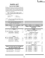
PARTS LIST
PARTS REPLACEMENT
Replacement parts which have these special safety characteristics
identified in this manual; electrical components having such features
are identified by
å
and shaded areas in the Replacement Parts Lists
and Schematic Diagrams. The use of a substitute replacement part
which dose no have the same safety characteristic as the factory
recommended replacement parts shown in this service manual may
create shock, fire or other hazards.
"HOW TO ORDER REPLACEMENT PARTS"
To have your order filled promptly and correctly, please furnish the
following informations.
1. MODEL NUMBER
2. REF. NO.
3. PART NO.
4. DESCRIPTION
in USA:
Contact your nearest SHARP Parts Distributor to order.
For location of SHARP Parts Distributor, Please call Toll-
Free; 1-800-BE-SHARP
★
MARK : SPARE PARTS-DELIVERY SECTION
'
MARK : X- RAY RELATED PARTS
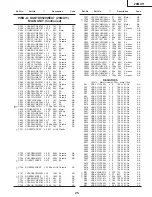
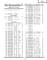
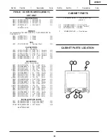
20MU11
çå
V101
VB48JLL40X/*
S
M Picture Tube
CC
çå
DY601
RCILH0105GJZZ
M Deflection Yoke
AY
å
L702
RCILG0099PEZZ
M Degaussing Coil
PMAGF3045CEZZ
J Magnet Ass'y
AK
QEARC2016PEZZ R Grounding Part
20MU11
çå
V101
VB48KRD89X/3E
M Picture Tube
çå
DY601 RCiLH0100MEZZ
M Deflection Yoke
AZ
å
L702
RCILG0099PEZZ
M Degaussing Coil
AM
MSPRT0002MEZZ M Spring for CRT
AA
(
20MU11
)
PMAGF3046CEZZ
J Magnet Ass'y
AK
QEARC2016PEZZ R Grounding Part
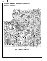
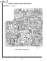
PRINTED WIRING BOARD ASSEMBLIES
(NOT REPLACEMENT ITEM)
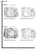
PWB-A
DUNTK9529WEX7
– MAIN Unit (
20MU11
)
—
PWB-A
DUNTK9532WEX0
– MAIN Unit (
20MU11
)
—
PWB-B DUNTK9530WEW6 – CRT Unit (
20MU11)
PWB-B DUNTK9533WEV4 – CRT Unit (
20MU11
,
—
TUNER
NOTE: THE PARTS HERE SHOWN ARE SUPPLIED AS AN
ASSEMBLY BUT NOT INDEPENDETLY
å
TU51
VTUVTST5UF670
M Tuner
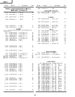
INTEGRATED CIRCUITS
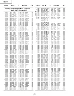
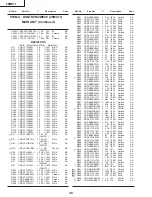
IC101
VHIKA78L05B-1+ J KA78L05B AD
çå
IC201 RH-iX3253CEZZ
J TA1268AN
AV
IC351 VHiTDA7233/-1
J TDA7233
AF
å
IC501 VHiTA8403K/-1
J TA8403K
AL
çå
IC701 VHiSTR301301E
J STR30130
AP
å
IC751 VHiKA7809
A
P-
1
R KA7809
A
P
AE
å
IC761 VHiKA7812Pi-1
R KA7812PI
AE
IC2001
RH-IX3297CEZZ
J TMPA8701CMF142
AX
IC2040 VHiPST994C/-1
J PST994C
AD
IC2101
VHIBR24C02/-1
J
BR
24C0
2
AF
TRANSISTORS
You can substitute "VS2SC2462-C-1" for "VS2SD601AR/-1".
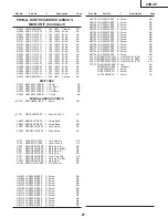
Q201
VS2SC2735//1E
J 2SC2735
AC
Q351
VS2SD601AR/-1
J 2SD601AR
AC
Q401
VS2SD601AR/-1
J 2SD601AR
AC
Q403
VS2SD601AR/-1
J 2SD601AR
AC
Q404
VS2SB709AR/-1
J 2SB709AR
AC
Q451
VS2SB709AR/-1
J 2SB709AR
AC
Q501
VS2SD601AR/-1
J 2SD601AR
AC
Q601
VS2SC2655Y/-1
J 2SC2655(Y)
AE
å
Q602
VS2SD2586//1E
J 2SD2586
AM
Ref. No.
Part No.
★
Description
Code
Ref. No.
Part No.
★
Description
Code
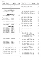
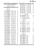
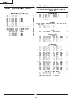
PWB-A:
DUNTK9529WEX7
(
20MU11
)
MAIN UNIT
20MU11
Summary of Contents for 20MU11
Page 4: ...4 LOCATION OF USER S CONTROL 20MU11 ...
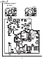
Page 10: ...10 6 5 4 3 2 1 A B C D E F G H CHASSIS LAYOUT Ë 20MU11 PWB B PWB A PWB B 20MU11 ...
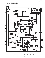
Page 11: ...11 6 5 4 3 2 1 A B C D E F G H BLOCK DIAGRAM 20MU11 ...
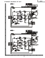
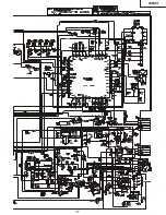
Page 13: ...6 5 4 3 2 1 A B C D E F G H 20MU11 SCHEMATIC DIAGRAM CRT UNIT DUNTK9533WEV4 DUNTK9530WEW6 13 ...
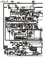
Page 14: ...14 20MU11 ...
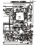
Page 15: ...15 20MU11 ...
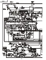
Page 16: ...16 20MU11 ...
Page 17: ...20MU11 17 ...
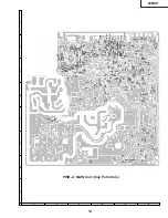
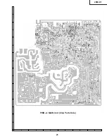
Page 19: ...19 6 5 4 3 2 1 A B C D E F G H PWB A MAIN Unit Chip Parts Side 20MU11 ...
Page 21: ...21 6 5 4 3 2 1 A B C D E F G H PWB A MAIN Unit Chip Parts Side 20MU11 ...

