background image

1

WA R NING

The chassis in this receiver is partially hot.  Use an isolation transformer between the line cord plug and power
receptacle, when servicing this chassis.  To prevent electric shock, do not remove cover.  No user - serviceable parts
inside.  Refer servicing to qualified service personnel.

SERVICE MANUAL

In the interes ts  of us er-s afety (R equired by s afety regulations  in s ome countries ) the s et s hould be res tored
to its  original condition and only parts  identical to thos e s pecified s hould be us ed.

MODE L S

COLOUR TELEVISION

Chassis No. GA-7S

FEATURES

 Multi 21 Systems, 100-CH program Memory

Full Auto Search System
NICAM/A2 STEREO

Blueback Function with Auto OFF

NTSC Colour Comb Filter Function

High Contrast Picture (Black Strecth Circuit)

CATV (Hyperband) Ready

White Temperature Select

SURROUND & AVL Function

OFF Timer & Child Lock
Hotel Mode & AV Mode (Movie/Music/News)

English Language OSD

S HAR P   C OR P OR AT ION

Page

¨

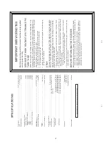
SPECIFICATIONS ............................................. 2

¨

IMPORTANT SERVICE NOTES ........................ 2

¨

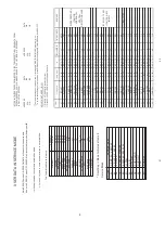
ADJUSTMENT PRECAUTIONS ........................ 3

¨

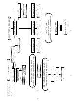
TROUBLE SHOOTING TABLE ....................... 14

¨

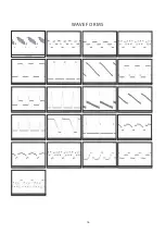
WAVEFORMS .................................................. 16

¨

SOLID STATE DEVICE BASE DIAGRAM ....... 17

¨

CHASSIS LAYOUT .......................................... 18

¨

BLOCK DIAGRAM ........................................... 19

¨

DESCRIPTION OF SCHEMATIC DIAGRAM .. 22

¨

SCHEMATIC DIAGRAM

¨

CRT UNIT ..................................................... 23

Page

¨

MAIN UNIT ................................................... 24

¨

REPLACEMENT PARTS LIST

¨

ELECTRICAL PARTS .................................. 26

¨

MISCELLANECOUS PARTS ....................... 30

¨

SUPPLIED ACCESSORIES......................... 30

¨

PACKING PARTS ......................................... 30

¨

CABINET PARTS ......................................... 30

CONTENTS

¨

21AXS500

Rear AV-IN/Out Terminal & Component In

Front AV-In Terminal & Sub-Woofer Output

¨

¨

¨

¨

¨

¨

¨

¨

¨

¨

¨

¨

¨

Sound Booter (Shakit)

LNASI (Antenna Booter)

¨

¨

Summary of Contents for 21AXS500

Page 1: ...CAM A2 STEREO Blueback Function with Auto OFF NTSC Colour Comb Filter Function High Contrast Picture Black Strecth Circuit CATV Hyperband Ready White Temperature Select SURROUND AVL Function OFF Timer Child Lock Hotel Mode AV Mode Movie Music News English Language OSD S HAR P COR POR ATION Page SPECIFICATIONS 2 IMPORTANT SERVICE NOTES 2 ADJUSTMENT PRECAUTIONS 3 TROUBLE SHOOTING TABLE 14 WAVEFORMS ...

Page 2: ... result of the repairs never forget to check for such high voltage after the work 3 Do not substitute a picture tube with unauthorizerd types and or brands which may cause excess X ray radiation BEFORE RETURNING THE RECEIVER Before returning the receiver to the user perform the following safety Checks 1 Inspect all lead dress to make certain that leads are not pinched or that hardware is not lodge...

Page 3: ...econds the initial values are automatically pres et 2 T he initial data are pres et as lis ted in page 5 8 3 Make s ure whether the data need to modify or not Initial data R efer to B US S E T UP DAT A Note O nce the chas s is has been as s embly together and in ready condition pleas e make s ure it s go through initialize proces s s ee s ect 2 above P rec aution If haven t done this initializatio...

Page 4: ...ess VOL UP VOL DOWN to modify adjust the data 01 RF AG C 0 63 UO C T V 23 AUTO 02 V SLOP E 0 63 UO C T V 31 ADJ 03 V SHI 50 0 63 UO C T V 36 ADJ 04 V AMP 50 0 63 UO C T V 20 ADJ 05 H SHI 50 0 63 UO C T V 30 ADJ 06 EW W 50 0 63 UO C T V 28 ADJ 07 E W PAR 50 0 63 UO C T V 36 ADJ 08 H PAR 0 63 UO C T V 30 ADJ 09 H BO W 0 63 UO C T V 30 ADJ 10 UPCOR PAR 0 63 UO C T V 42 ADJ 11 LOCOR PAR 0 63 UO C T V ...

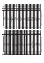
Page 5: ...VOL OPTION_LNA _BOOSTER PHI FORCE LCKEY_SRV ENTER ERR_XRAY AGN DSGLS_SEL TION OPTION SHAKIT SAVE MODE DSK_NOT PAL_AV INCL_AV EER 1 8 SUP DSG CBS OPTION _MPIN PICTURE_NR MUISIC 92 1B 0C 49 E4 45 F0 01 LOUDNES S BOOSTER PICTURE_NR MOVIE PICTURE_NR NEWS 00 FF 00 FF 00 BF 00 7D 00 F5 00 7F 00 7D 00 33 FIX FIX FIX FIX BUS SETUP BUS SETUP BUS SETUP FIX Note Highlighted item cannot be adjusted due fixed ...

Page 6: ... 00 3F FIX 0 0 4 5 0 0 4 6 0 0 4 7 00 FF 00 FF FIX FIX E W PAR 60 30 VER SHI P60 VER AMP P60 0 0 4 4 24 25 EW W 60 29 20 FIX 00 3F 1F FIX 00 3F DRI RLW DVD 57 DRI GLW DVD 58 DRI BLW DVD 59 CUT RLW DVD 60 CUT GLW DVD 61 NVM MODE ITEM 3 5 ADDRESS HEX DATA D7 D6 D5 D4 D3 D2 D1 D0 MICON DEFAULT hex EEPROM RANGE hex REMARK 0 0 8 1 0 0 8 2 0 0 8 3 0 0 B 0 0 0 B 1 0 0 B 2 0 0 B 3 0 0 8 8 0 0 8 9 0 0 8 A ...

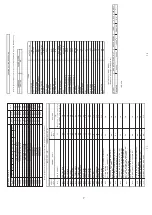
Page 7: ...3 1F F IX 076 U BASS_MOV 0C FIX 077 U TREBLE_MUSC 0D FIX 079 U TREBLE_MOV 0C F IX 086 OSD 0D FIX 095 SHAKIT _MER1 71 FIX 096 SHAKIT_MER2 76 F IX 097 SHAKIT_MER3 78 FIX 098 SHAKIT_MER4 82 FIX 0A4 AV2_BRI 24 FIX 0BF LAST 05 F IX 0C9 SHAKIT_MER5 8A FIX 0CA SHAKIT_MER6 91 FIX SURROUND MUSIC OPTION OPTION 4C FIX 0F9 OSD AVL TREBLE OPTION LIMIT BASS 6FE OPTION VOL LNA BOOTER SHAKIT OPTION AUTO LOUDNESS ...

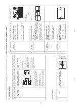
Page 8: ...condition 3 Adjust the focus control to get the best focusing ADJUSTMENT CONDITION PROCEDURE Focusing Point middle of center and edge of monoscope pattern 3 HORIZONTAL VERTICAL DEFLECTION LOOP ADJUSTMENT NO ADJUSTMENT POINT WAVEFORM OR OTHERS 1 V SLOPE I2C BUS CONTROL ADJUSTMENT CONDITION PROCEDURE 1 Receive Monoscope Pattern Signal PAL 50 Hz 2 Choose the service data 02 V SLOPE 3 Adjust the V SLO...

Page 9: ...T ADJUSTMENT NO ADJUSTMENT POINT WAVEFORM OR OTHERS 1 SCREEN ADJUSTMENT I2C BUS CONTROL ADJUSTMENT C ONDITION PROCEDURE 1 Make sure the following items are in INITIAL DATA before adjust CR T cutoff a 15 DRI RS 32 b 16 DRI GS 32 c 17 DRI BS 32 d 18 CUT RS 16 e 19 CUT GS 16 f 20 CUT BS 16 f 21 SUB BRI 24 g 22 SUB CON 59 h 32 CUT OFF 25 i 35 BLOC 4 2 Switch TV to video mode blue back off with no sign...

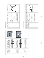
Page 10: ...ervice Luminanc e mode cd m2 Upper limit Lower limit E nable 150 0 10 10 Disable 150 0 20 10 Toleranc e cd m2 5 PAL CHROMA ADJUSTMENT 6 NTSC CHROMA ADJUSTMENT NO ADJUSTMENT POINT WAVEFORM OR OTHERS 1 SUB COLOUR I2C BUS CONTROL ADJUSTMENT C ONDITION PROCEDURE 1 Receive the PAL Split Color Bar signal 2 Make the image normal with the remote controller 3 Connect the oscilloscope to TP47R R863 RED OUT ...

Page 11: ...her the CONTRAST effect is OK or not 2 COLOUR Key 1 Receive Colour Bar signal 2 Press to Menu mode then select Picture Mode and set to select COLOUR 3 Press Volume Up Down key to check whether the COLOUR effect is OK or not 3 BRIGHTNESS Key 1 Receive Monoscope Pattern signal 2 Press to Menu mode then select Picture Mode and set to select B RIGHTNESS 3 Press Volume Up Down key to check whether the ...

Page 12: ... SECAM mode Check again its colour so that it is working properly 3 Receive NTSC 4 43 signal press COLOUR SYSTEM key to select modes except NTSC 4 43 check the COLOUR is not working properly Then select the NTSC 4 43 mode Check again its colour so that it is working properly 4 Receive NTSC 4 43 3 58 COLOUR BAR signal thru AV press COLOUR SYSTEM key to select modes except N4 43 3 58 check the COLOU...

Page 13: ...13 2 10 SHOCK TEST CHECKING NO ADJUSTMENTPOINT ADJUSTMENT CONDITION PROCEDURE WAVEFORM OR OTHERS 1 SHOCK TEST 1 Hit at the top of TV set for two time 2 Check TV set not damage and TV operation operate correctly ...

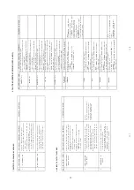
Page 14: ...l Check Q601 Q602 and Q803 NO PICTURE NO SOUND No snow noise Does noise or signal appear at pin 34 of IC1001 Noise increases but no signal is received Check the tuner supply voltage LB must approx 5V BT must be approx 33V And check the CH preset data Check the tuner AGC at JA402 Check IC1001 and related circuit Check pin 1 of SF201 Tuner and related circuit Check pin 40 at IC1001 and related circu...

Page 15: ...nal V ertical linearity and s ize are abnormal DE F E C T IV E V E R T IC A L A MP A ND V E R T IC A L L INE A R IT Y R e adjus t vertical s ize B us Data C heck R 503 R 506 and R 521 NO S P E C IF IC C OL OUR Is s ome colour produced in B W broadcas t reception Is the white balance properly adjus ted R e adjus t the white balance T he picture colour is yellow T he picture colour is magenta T he p...

Page 16: ...44 Vp p H 8 3 97 Vp p H 6 0 944 Vp p V 6 5 99 Vp p H 5 4 43 Vp p H 9 42 1 Vp p H 10 1 102 KVp p H 11 64 9 Vp p V 12 1 94 Vp p V 16 2 52 Vp p H 15 5 99 Vp p V 14 525 Vp p 13 156 5 Vp p H 17 2 32 Vp p H 21 126 Vp p H 18 2 63 Vp p H 19 131 5 Vp p H 20 112 5 Vp p H ...

Page 17: ...17 S OLID S TATE DE VICE B AS E DIAGR AM ...

Page 18: ...18 ...

Page 19: ...19 B LOCK DIAGR AM CR T UNIT S HAK IT UNIT ...

Page 20: ...21 20 B LOCK DIAGR AM MAIN UNIT ...

Page 21: ...ignal of 1 0V peak applied at pin 24 of IC201 2 Approximately 4V AGC bias SAFETY NOTES 1 DISCONNECT THE AC PLUG FROM THE AC OUTLET BEFORE REPLACING PARTS 2 SEMICONDUCTOR HEAT SINKS SHOULD BE REGARDED AS POTENTIAL SHOCK HAZARDS WHEN THE CHASSIS IS OP ERATING IMPORTANT SAFETY NOTICE PARTS MARKED WITH ARE IMPORTANT FOR MAINTAINING THE SAFETY OF THE SET BE SURE TO RE PLACE THESE PARTS WITH SPECIFIED O...

Page 22: ...23 1 2 3 4 5 6 7 8 9 10 A B C D E F G H I J SCHEMATIC DIAGR AM CR T UNIT ...

Page 23: ...25 24 1 2 3 4 5 6 7 8 9 10 A B C D E F G H I J 11 12 13 14 15 16 17 18 19 SCHEMATIC DIAGRAM MAIN UNIT ...

Page 24: ...26 1 2 3 4 5 6 7 8 9 10 A B C D E F G H I J SCHEMATIC DIAGR AM SHAK IT UNIT ...

Reviews: