11
21HS-50H
•
COLOUR ADJUSTMENT PROCEDURE
The following adjustments should only be carried out when the CRT or IC801 are replaced.
NOTES:
•
This adjustment must be done after warming up the unit for 30 minutes or longer with a beam current over 700
µA.
•
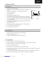
The red value «DRI-RS» should be fixed to 42. (Refer to “How to access service mode” section).
•
«DRI-GS» adjustment alters “Y” co-ordinate.
•
«DRI-BS» adjustment alters “X” and “Y” co-ordinates.
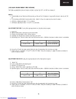
ADJUSTMENT METHOD 1 (using the signal generator, varying the picture signal)
1. Adjust G2.
2. Input a white pattern with burst signal from SCART.
3. Position the colorimeter in the centre of screen.
4. Adjusting input signal level, select a luminance of 70 nits.
5. Operate again in “service mode“ and select «DRI-GS» and/or «DRI-BS» locations to obtain colour co-ordinates:
6. Re-set the TV with the mains switch button to store the adjustment and exit service mode.
7. Check colour co-ordinates “X” and “Y” at 20 a 120 Nits. It may be necessary to repeat the same procedure to
obtain the above values.
ADJUSTMENT METHOD 2 (using the signal generator, with a fixed picture signal)
1. Adjust G2.
2. Tune a white pattern with burst signal.
3. Operate in “service mode”:
4. Using «SUB-CON», select a luminance of 70 nits.
5. Operate again in “service mode“ and select «DRI-GS» and/or «DRI-BS» locations to obtain colour co-ordinates:
6. Select «SUB-CON». Return data to “63”.
7. Re-set the TV with the mains switch button to store the adjustment and exit service mode.
8. Check colour co-ordinates “X” and “Y” at 20 a 120 Nits. It may be necessary to repeat the same procedure to
obtain the above values.
X
Y
Screen temperature
0.290
±
0.015
0.284
±
0.015
8900º K-20 MPCD
X
Y
Screen temperature
0.290
±
0.015
0.284
±
0.015
8900º K-20 MPCD
Summary of Contents for 21HS-50H
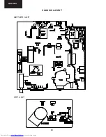
Page 12: ...12 21HS 50H CHASSIS LAYOUT MOTHER UNIT CRT UNIT ...
Page 27: ...27 21HS 50H ...
Page 31: ...31 21HS 50H SCHEMATIC DIAGRAM OF CRT F7341N0 00 Version 1 I H G F E D C B A 2 3 4 5 6 7 ...
Page 32: ...32 21HS 50H CRT UNIT BLOCK DIAGRAM 1 I H G F E D C B A 2 3 4 5 6 7 ...
Page 33: ...33 21HS 50H MOTHER UNIT BLOCK DIAGRAM 1 I H G F E D C B A 2 3 4 5 6 7 ...
Page 43: ...43 21HS 50H NOTES ...


