background image

Standard DIN45325 

plug (IEC169-2) 

75-ohm 

coaxial cable 
(round cable) 

(not supplied)

300-ohm  
twin-lead  
flat feeder  
(not supplied)

75-ohm  
impedance  
converter  
(not supplied)

Antenna in

TV

Antenna in

TV

VCR

To antenna 
in terminal

To RF out 
terminal

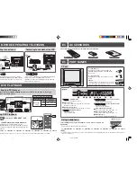
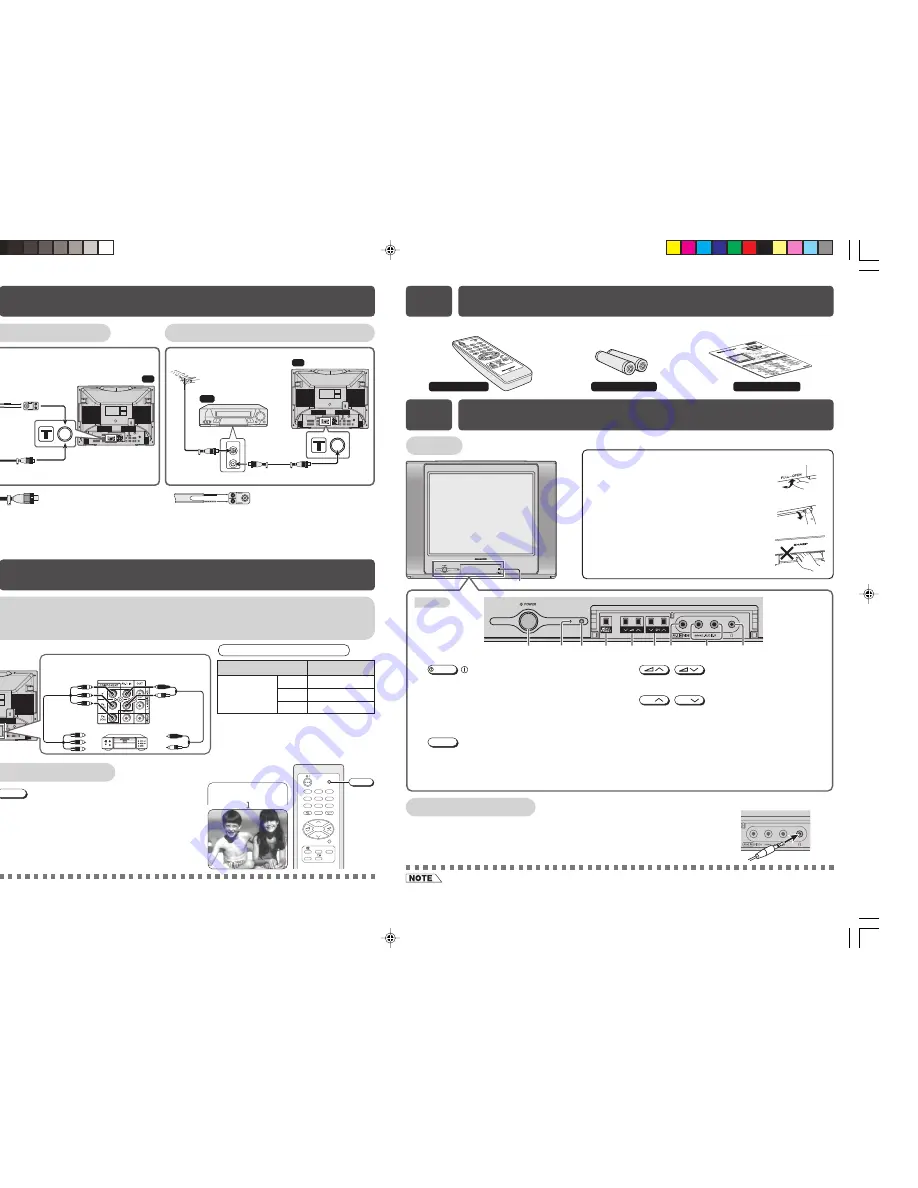
Connecting to a DVD player

The DVD input terminals (COMPONENT-IN) on the rear of the TV can be used to input high-
quality images from a DVD player.

If your outdoor antenna uses a 75-ohm coaxial
cable with a standard DIN45325 plug (IEC 169-2),
plug it into the antenna jack at the rear of the set.

[ Behind the door ]

Using headphone

Insert headphone plug into headphone jack to listen to audio with
headphone.

• The audio from the speakers is turned off.

• When using the RF terminal connection, set the TV to channel zero to make initial adjustments for the VCR.

• To avoid injuring your hearing, do not put on the headphone before plugging them into the headphone jack and before

the power is turned on.

E4

ACCESSORIES

E2

BEFORE OPERATING TELEVISION

Connecting to an antenna

Connecting to an antenna via a VCR

E3

DVD PLAYBACK

If your outdoor antenna uses a 300-ohm twin-lead
flat feeder, connect a 300-ohm to 75-ohm
impedance converter and plug it into the antenna
jack at the rear of the set.

TV

DVD input terminals

To colour-difference
(component video)
out terminals

To audio out

(L/R) terminals

DVD player

Green : To Y
Blue  : To P

B

 (C

B

)

Red 

: To P

R

 (C

R

)

Red  : To AUDIO IN (R)
White : To AUDIO IN (L)

Connecting the video terminals

DVD input terminals

DVD player

COMPONENT-IN

VIDEO

Y

Y or Y/Y

P

B

(C

B

)

P

B

(C

B

) or B-Y/Pb

P

R

(C

R

)

P

R

(C

R

) or R-Y/Pr

Watching DVD Playback

!

Press 

TV/VIDEO

 to select “COMPONENT”, DVD

input screen.

@

Turn on the DVD player and begin playback.

• When connecting the TV to a DVD player via the

COMPONENT-IN terminals, the video and audio from the
DVD player cannot be output through the Audio/Video out
terminals on the TV.

TV/VIDEO

0

4

7

2

8

3

6

9

CH

CH

1

5

MENU

SURROUND

LANGUAGE

NORMAL

TV/VIDEO

C O M P O N E N T

The following accessories are included with this television.

Remote Control

Size-AA batteries

Operation manual

E5

PART NAMES

TV set

Door

Bottom

MENU/PRESET

/

CH

CH

/

POWER

!

!

@

$

% ^

@ #

&

*

(

POWER switch

Turns on and off the main power.

%

Volume up/down buttons

Adjusts the volume. 
Makes adjustments in PRESET.

^

Channel up/down buttons

Selects the channels. 
Tunes or sets the channels.

$

MENU/PRESET button

Tunes the channels. 
Used for MENU setup.

Power indicator 

Power can be turned on by the remote control when  
the indicator is dimly lit.

#

Infrared sensor window 

Receives the infrared wave from the remote control.

&

Video input terminal (AV-2 IN) 

Connects to a camcorder, video game, etc.

*

Audio input terminals (AV-2 IN) 

Connects to a camcorder, video game, etc. 


(

Headphone jack 

Use to listen to the audio with headphone.

To open the door

Using the projection located under the
“PULL-OPEN” indication, pull and lift the
door open.

To close the door

Using the projection, lower the door until
closed.

Caution:

• When opening or closing the door, do not insert

your fingers into the gap between the door and
front panel. This may result in an injury.

21K-FD1SA[EN]

13/9/05, 12:22 PM

2

Summary of Contents for 21K-FD1SA

Page 1: ...c shock do not remove the back of the cabinet This TV set contains dangerous voltage Power cord protection To prevent electrical shock do not subject the AC power cord to damage by bending or twisting it or by placing heavy items on top of it and do not place the AC power cord under the TV set If the AC power cord becomes damaged unplug it from the wall outlet immediately and call your dealer for ...

Page 2: ...yer COMPONENT IN VIDEO Y Y or Y Y PB CB PB CB or B Y Pb PR CR PR CR or R Y Pr ng DVD Playback TV VIDEO to select COMPONENT DVD creen n the DVD player and begin playback ecting the TV to a DVD player via the NT IN terminals the video and audio from the cannot be output through the Audio Video out n the TV TV VIDEO 0 4 7 2 8 3 6 9 CH CH 1 5 MENU SURROUND LANGUAGE NORMAL TV VIDEO COMPONENT The follow...

Page 3: ...econds after the volume has been adjusted Using CH CH Press CH and channels change as shown below 1 2 98 99 AV1 or COMPONENT AV2 0 1 2 Press CH and channels change as shown below 1 0 AV2 AV1 or COMPONENT 99 98 2 1 0 With the number buttons on remote control To select a one digit channel such as 5 press 5 If 5 is indicated press to select one digit input and then press 5 again To select a two digit...

Page 4: ...er buttons to select the desired channel and then set SKIP to OFF FINE The frequency changes to allow fine tuning BOOSTER Picture quality may improve in regions with weak signal strength using this function If ON is selected and the picture quality is still not good enough please switch to ON If signal strength is strong enough for the selected channel the effect is negligible and may produce inst...

Page 5: ...ning time appears on the screen A flashing display of the remaining time appears during the last few seconds When the preset length of time has passed the TV set enters the Standby mode Off timer Automatically turns power off after a set length of time has passed Repeat step 1 to 3 of OFF TIMER Press CH CH to select ON Press to set time for TV to turn on Maximum time that can be preset is 12 hours...

Page 6: ...much noise may activate BLUE BACK despite the presence of a gnal To continue watching TV under these conditions switch BLUE BACK to OFF er is set the OFF TIMER setting has priority over BLUE BACK E10 FEATURES Continued TIMER SETTING Continued FEATURES Child lock Preventing children from watching TV Setting the CHILD LOCK mode For the first time Press MENU to call MENU screen Press CH CH to select ...

Page 7: ... the most of the speakers performance ON Setting to this mode during monaural signal reception creates monaural sound that is similar to stereophonic sound Surround sound Produces a virtual surround sound from the TV s speakers SURROUND ON SURROUND ON SURROUND OFF TV VIDEO TV 0 4 7 2 8 3 6 9 CH CH 1 5 MENU SURROUND LANGUAGE NORMAL SURROUND Example use of front terminals Connecting to video equipme...

Page 8: ...3 58 4 5 MHz 50 Hz Reception Channels PAL B G VHF E2 E12 ch SECAM B G UHF E21 E69 ch PAL D K VHF C1 C12 ch R1 R12 ch SECAM D K K1 UHF C13 C57 ch R21 R69 ch PAL I VHF B J ch UHF 21 69 ch Hong Kong NTSC VHF 2 13 ch U S 1 12 ch Japan UHF 14 69 ch U S 13 62 ch Japan CATV S1 S20 ch S21 S41 ch Hyper Receiving Frequency 48 25 MHz 863 25 MHz Channel Tuning 100 Channel Electronic Tuner with Full Auto Tunin...

Reviews: