10
AK - 44
CHASSIS
(2).
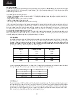
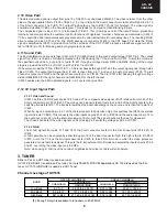
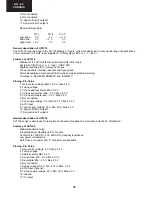
Enough margin is available to tune up to 863.25 MHz.
Noise
Typical
Max.
Gain
Min. Typical
Max.
Low band: 5 dB
9 dB
All channels:
38 dB 44 dB
52 dB
Mid band:
5dB
9 dB
Gain Taper (of-air channels):
8 dB
High band: 6 dB
9 dB
Channel Coverage UV1336
BAND CHANNELS FREQUENCY
RANGE (MHz)
Low Band
2 to D
55.25 to 139.25
Mid Band
E to PP
145.25 to 391.25
High Band
QQ to 69
397.25 to 801.25
Noise
is typically 6 dB for all channels.
Gain
is minimum 38 dB and maximum 50 dB for all
channels.
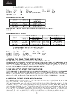
Channel Coverage of UV1315
OFF-AIR CHANNELS
CABLE CHANNELS
FREQUENCY FREQUENCY
BAND
CHANNELS
RANGE (MHz)
CHANNELS
RANGE (MHz)
Low Band
E2 to C
48.25 to 82.25
(1)
S01 to S10
69.25 to 168.25
Mid Band
E5 to E12
175.25 to 224.25
S11 to S39
231.25 to 447.25
High Band
E21 to E69
471.25 to 855.25
(2)
S40 to S41
455.25 to 463.25
(1).
Enough margin is available to tune down to 45.25 MHz.
(2).
Enough margin is available to tune up to 863.25 MHz.
Noise
Typ. Max.
Gain
Min. Typ.
Max.
Low band
6 dB 9 dB
All Channels
38 dB 44 dB
50 dB
Mid band
6 dB 10 dB
Gain Taper
8 dB
High band 6 dB 11 dB
(off-air channels)
4. DIGITAL TV SOUND PROCESSOR MSP34X0
The MSP 34x0G is designed to perform demodulation of FM or AM-Mono TV sound.
Alternatively, two-carrier FM systems according to the German or Korean terrestrial specs or the satellite specs can be
processed with the MSP 34x0G. Only the MSP 3410 does digital demodulation and decoding of NICAM-coded TV
stereo sound. The MSP 34x0G offers a powerful feature to calculate the carrier field strength which can be used for
automatic standard detection (terrestrial) and search algorithms (satellite).
5. SOUND OUTPUT STAGE TDA7266L/TDA7266
TDA7266L is used as the AF output amplifier for mono applications. It is supplied by +12 VDC coming from a separate
winding in the SMPS transformer. An output power of 4 W (THD = 0.5 %) can be delivered into an 16 ohm load.
TDA7266 is used as the AF output amplifier for stereo applications. It is supplied by +12 VDC coming from a separate
winding in the SMPS transformer. An output power of 2*4W (THD = 0.5 %) can be delivered into an 16 ohm load.
6. VERTICAL OUTPUT STAGE WITH TDA8174A
The TDA8174A is a power amplifier circuit for use in 90° and 110° color deflection systems for 25 to 200 Hz field
frequencies, and for 4 : 3 and 16 : 9 picture tubes.
IC403 generates a vertical pulse signal VER_OUT and V_AMP that are fed to IC600 (the vertical stage IC). IC600 is
supplied by a 26V DC via diode D610. It generates its own ramp signal and based on the V_AMP & VER_OUT signals
it produces the vertical deflection signals that are fed to connector PL601. Vertical linearity adjustment is controlled by
Q604, which is driven by the PWM output of IC501 at pin 49. Vertical position adjustment is conducted by Q606 derived
by the VER_OUT signal. Switching Q606 will change the DC voltage on VOUT_2 pin, which will either lower or higher
the picture. A DC level is supplied at VOUT_2 via D614 to stabilise the picture and make its position changeable.
Summary of Contents for 21LT-45SES
Page 6: ...6 21LT 45S CHASSIS LAYOUT Mother Unit CRT Unit ...
Page 48: ...36 AK 44 CHASSIS 1 I H G F E D C B A 2 3 4 5 6 7 18 4 Schematic Diagram of Audio Circuit ...
Page 52: ...40 AK 44 CHASSIS 1 I H G F E D C B A 2 3 4 5 6 7 18 7 Schematic Diagram of CRT Socket Circuit ...
Page 55: ...43 AK 44 CHASSIS Notes ...

