15
AK - 44
CHASSIS
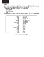
STV224X Video processor
The STV2246/2247/2248 are fully bus controlled ICs for TV including PIF, SIF, luma, Chroma and deflection processing.
Used with a vertical frame booster (TDA1771 or TDA8174 for 90° chassis, STV9306 for 110° chassis), they allow the
design of multi-standard sets with very few external components and no manual adjustments.
SIFIN1
SIFIN2
AGCSIFCAP
V
REFIF
AGCPIFCAP
PIFIN1
PIFIN2
TUNERAGCOUT
IFPLL
GND
IF
AM/FMOUT/SC
V
CCIF
INTCVBSOUT
EXTAUDIOIN
PIFLC1
PIFLC2
V
CC2
CVBSIN1
GND2
CVBSIN2
BS
Y/CVBSIN3
CHR
APR
BEXT/Cb
GEXT/Y
REXT/Cr
FBEXT
FMCAP
AUDIOOUT
GNDD
V
CCD
SDA
SCL
SLPF
LFB/SSC
HOUT
VERT
BCL/SAF
V
CC1
CVBSOUT2
GND1
X1/VAMP/CHROUT
CLPF
XTAL1
XTAL2
XTAL3/BTUN
ROSD
GOSD
BOSD
I
CATH
ROUT
GOUT
BOUT
NTBC/CVBSOUT1
FBOSD/HC
1
2
3
4
5
6
7
8
9
10
11
12
13
14
15
16
17
18
19
20
21
22
23
24
25
26
27
28
56
55
54
53
52
51
50
49
48
47
46
45
44
43
42
41
40
39
38
37
36
35
34
33
32
31
30
29
Figure 2. Pin connections STV224X/8X (SDIP56)
UV1315, UV1316, UV1336
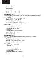
General description of UV1315
The UV1315 tuner belongs to the UV 1300 family of tuners, which are designed to meet a wide range of applications.
It is a combined VHF, UHF tuner suitable for CCIR systems B/G, H, L, L’, I and I’.
Features of UV1315
Member of the UV1300 family small sized UHF/VHF tuners
Systems CCIR: B/G, H, L, L’, I and I’; OIRT: D/K
Voltage synthesized tuning (VST)
Off-air channels, S-cable channels and Hyper-band
Standardized mechanical dimensions and pinning
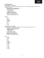
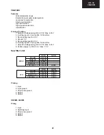
Pinning, Pin Value
1. Gain control voltage (AGC): 4.0 V, Max: 4.5 V
2. Tuning voltage
3. High band switch: 5 V, Min: 4.75 V, Max: 5.5 V
4. Mid band switch: 5 V, Min: 4.75 V, Max: 5.5 V
5. Low band switch: 5 V, Min: 4.75 V, Max: 5.5 V
6. Supply voltage: 5 V, Min: 4.75 V, Max: 5.5 V
7. Not connected
Summary of Contents for 21LT-45SES
Page 6: ...6 21LT 45S CHASSIS LAYOUT Mother Unit CRT Unit ...
Page 48: ...36 AK 44 CHASSIS 1 I H G F E D C B A 2 3 4 5 6 7 18 4 Schematic Diagram of Audio Circuit ...
Page 52: ...40 AK 44 CHASSIS 1 I H G F E D C B A 2 3 4 5 6 7 18 7 Schematic Diagram of CRT Socket Circuit ...
Page 55: ...43 AK 44 CHASSIS Notes ...

