27
25WF30
WAVEFORMS
Pin 1 Vp-p=2.46v
Pin 2 Vp-p=1.8v
Pin 3 Vp-p=1.7v
Pin 4 Vp-p=2.04v
Pin 5 Vp-p=58.4v
Pin 6 Vp-p=288v
Pin 7 Vp-p=1090v
Pin 8 Vp-p=10v
Pin 9 Vp-p=4.64v
Pin 10 Vp-p=1.0v
Pin 11 Vp-p=1.0v
Pin 12 Vp-p=4.6v
Pin 13 Vp-p=3.96v
Pin 14 Vp-p=3.88v
Pin 15 Vp-p=150.0v
Pin 16 Vp-p=150.0v
Pin 17 Vp-p=150.0v
Pin 18 Vp-p=448.0v
Summary of Contents for 25WF30
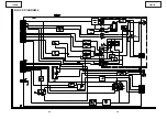
Page 18: ...6 5 4 3 2 1 A B C D E F G H 18 25WF30 CHASSIS LAYOUT ...
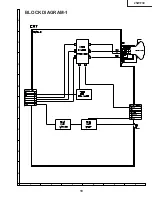
Page 19: ...6 5 4 3 2 1 A B C D E F G H 19 25WF30 BLOCK DIAGRAM 1 ...
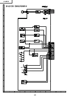
Page 23: ...6 5 4 3 2 1 A B C D E F G H 26 25WF30 BLOCK DIAGRAM 5 ...
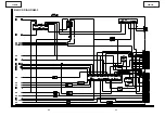
Page 26: ...6 5 4 3 2 1 A B C D E F G H 29 25WF30 SCHEMATIC DIAGRAM CRT Unit ...
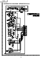
Page 30: ...6 5 4 3 2 1 A B C D E F G H 36 25WF30 SCHEMATIC DIAGRAM OPERATION Unit ...
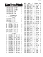
Page 35: ...6 5 4 3 2 1 A B C D E F G H 44 25WF30 PWB D OPERATION Unit Wiring Side ...

