
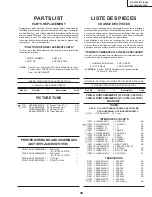


Ref. No.
Part No.
★
Description
Code
Ref. No.
Part No.
★
Description
Code
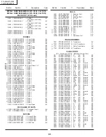
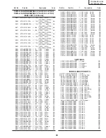
31
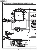
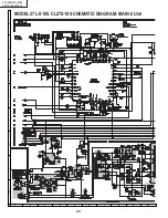
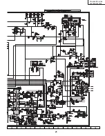
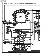
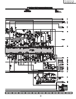
27L-S100/27L-S180
CL27S10/CL27S18
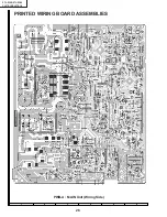
PWB-A: DUNTK9806WEK4 (27L-S100, CL27S10)
PWB-A: DUNTK9806WEK5 (27L-S180, CL27S18)
MAIN UNIT (Continued)
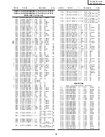
C501
VCKYPA2HB102K
J 1000p 500V
Ceramic
AA
C502
VCEA0A1VW108M J 1000
35V
EL.
AD
C510
VCFYSA1JA564J
J 0.56
63V
Mylar
AE
C511
VCKYPA2HB391K
J 390p
500V
Ceramic
AA
C512
RC-QZA473TAYK
J 0.047
50V
Mylar
AB
C513
RC-QZA103TAYK
J 0.01
50V
Mylar
AA
C514
VCEA0A1VW107M J 100
35V
EL.
AC
C515
VCEA0A1HW474M J 0.47
50V
EL.
AB
C516
VCSATA1VE684K
J 0.68
35V
Tantalum
AC
C517
VCEA0A1VW108M J 1000
35V
EL.
AD
C518
VCFYSA1JA473J
J 0.047
63V
Mylar
AC
C551
VCSATA1CE225K
J 2.2
16V
Tantalum
AB
C552
VCEA0A1HW225M J 2.2
50V
EL.
AB
C606
VCKYPA2HB561K
J 560p
500V
Ceramic
AA
C607
VCKYPA1HB472K
J 4700p 50V
Ceramic
AA
çå
C610
VCFPVC3CA772H M 7700p 1.6kV
M-Poly.
çå
C611
VCFPVC3CA772H M 7700p 1.6kV
M-Poly.
C615
VCKYPA2HB102K
J 1000p 500V
Ceramic
AA
C623
VCEA4A2EN106M
J 10
250V
EL.
AD
C631
VCEA0A1HW335M J 3.3
50V
EL.
AB
C632
RC-QZA103TAYK
J 0.01
50V
Mylar
AA
C633
VCEA0A1CW477M J 470
16V
EL.
AC
C652
VCEA0A1HW106M J 10
50V
EL.
AB
C653
VCEA0A1HW106M J 10
50V
EL.
AB
C680
VCFPVC2DB474J
M 0.47
200V
M-Poly.
C682
VCKYPA2HB331K
J 330p
500V
Ceramic
AA
å
C701
RC-FZ017SCEZZ
J 0.22
AC250V Plastic
AD
C702
RC-KZ0029CEZZ
J 0.01
AC250V Ceramic
AC
C703
RC-KZ0029CEZZ
J 0.01
AC250V Ceramic
AC
å
C705
RC-EZ0800CEZZ
J 560
200V
EL.
AQ
å
C706
RC-KZ0092GEZZ
J 0.0033 AC250V Ceramic
AC
C707
VCFPVC3CA222H
J 2200p 1.6kV
M-Poly.
AE
C708
VCCSPA1HL471J
J 470p
50V
Ceramic
AA
C709
VCEA0A1VW107M J 100
35V
EL.
AC
C710
RC-QZA102TAYJ
J 1000p
Mylar
AB
C717
VCKYPA2HB472K
J 4700p 500V
Ceramic
AB
C718
VCKYPA2HB472K
J 4700p 500V
Ceramic
AB
C722
RC-QZA104TAYK
J 0.1
50V
Mylar
AB
å
C723
RC-EZ0724CEZZ
J 100
160V
EL.
AG
å
C725
RC-EZ0809CEZZ
J 220
160V
EL.
AL
C726
RC-KZ0338CEZZ
J Capacitor
AD
C727
RC-KZ0338CEZZ
J Capacitor
AD
C729
VCEA0A1CW106M J 10
16V
EL.
AB
å
C730
RC-EZ0385CEZZ
J 1000
15V
EL.
AE
å
C731
RC-EZ0385CEZZ
J 1000
15V
EL.
AE
C732
VCKYPA2HB102K
J 1000p 500V
Ceramic
AA
C741
VCKYPA2HB102K
J 1000p 500V
Ceramic
AA
C742
VCKYPA2HB102K
J 1000p 500V
Ceramic
AA
C753
VCEA0A1CW107M J 100
16V
EL.
AC
C755
VCEA0A1CW476M J 47
16V
EL.
AB
C772
VCEA0A1VW477M J 470
35V
EL.
AB
C801
RC-QZA223TAYK
J 0.022
50V
Mylar
AB
C802
VCEA0A1HW474M J 0.47
50V
EL.
AB
C803
VCCCCY1HH110J
J 11p
50V
Ceramic
AA
C804
VCKYCY1CB104K
J 0.1
16V
Ceramic
AB
C805
VCKYCY1CB104K
J 0.1
16V
Ceramic
AB
C806
VCKYCY1CB104K
J 0.1
16V
Ceramic
AB
C807
VCCCCY1HH221J
J 220p
50V
Ceramic
AA
C808
VCKYCY1HB102K
J 1000p 50V
Ceramic
AA
C901
VCEA0A1HW335M J 3.3
50V
EL.
AB
(27L-S180, CL27S18)
C902
VCEA0ACW476M
J 47
16V
EL.
AB
(27L-S180, CL27S18)
C903
VCEA0A1HW335M J 3.3
50V
EL.
AB
(27L-S180, CL27S18)
C908
VCEA0A1HW225M J 2.2
50V
EL.
AB
C909
VCEA0A1HW225M J 2.2
50V
EL.
AB
C910
VCKYCY1HB681K
J 680p
50V
Ceramic
AA
(27L-S180, CL27S18)
C911
VCKYCY1HB681K
J 680p
50V
Ceramic
AA
(27L-S180, CL27S18)
C922
VCEA0A1HW335M J 3.3
50V
EL.
AB
(27L-S180, CL27S18)
C923
VCEA0A1HW335M J 3.3
50V
EL.
AB
(27L-S180, CL27S18)
C931
VCKYCY1EB183K
J 0.018
25V
Ceramic
AA
(27L-S180, CL27S18)
C932
VCKYCY1EB183K
J 0.018
25V
Ceramic
AA
(27L-S180, CL27S18)
C951
VCEA0A1HW106M J 10
50V
EL.
AB
C952
VCEA0A1HW106M J 10
50V
EL.
AB
C954
VCKYCY1HF103Z
J 0.01
50V
Ceramic
AA
C955
VCEA0A1CW106M J 10
16V
EL.
AB
C2001 VCCCCY1HH101J J 100p
50V
Ceramic
AA
C2002 VCCCCY1HH101J J 100p
50V
Ceramic
AA
C2040 VCEA0A1AW107M J 100
10V
EL.
AB
C2041 VCEA0A1HW105M J 1.0
50V
EL.
AB
C2060 VCKYCY1CB104K J 0.1
16V
Ceramic
AB
C2061 VCCCCY1HH101J J 100p
50V
Ceramic
AA
C2062 VCEA0A1AW107M J 100
10V
EL.
AB
C2201 VCKYCY1HB152K J 1500p 50V
Ceramic
AA
C2202 VCCCCY1HH390J J 39p
50V
Ceramic
AA
C2601 VCEA0A1HW475M J 4.7
50V
EL.
AB
C2602 VCCCCY1HH101J J 100p
50V
Ceramic
AA
C3001 VCE9GA1HW475M J 4.7
50V
EL.(N.P)
AB
C3002 VCKYCY1HB562K J 5600p 50V
Ceramic
AA
C3003 RC-QZA123TAYK
J 0.012
50V
Mylar
AB
C3004 VCEA0A1HW105M J 1.0
50V
EL.
AB
C3005 VCEA0A1HW475M J 4.7
50V
EL.
AB
C3006 VCEA0A1HW106M J 10
50V
EL.
AB
C3007 VCEA0A1HW475M J 4.7
50V
EL.
AB
C3008 VCKYCY1HF103Z
J 0.01
50V
Ceramic
AA
C3009 VCEA0A1CW227M J 220
16V
EL.
AC
C3010 VCE9GA1HW475M J 4.7
50V
EL.(N.P)
AB
C3011 VCEA0A1HW475M J 4.7
50V
EL.
AB
C3012 VCE9GA1HW475M J 4.7
50V
EL.(N.P)
AB
C3013 VCKYCY1HB272K J 2700p 50V
Ceramic
AA
C3014 RC-QZA473TAYK
J 0.047
50V
Mylar
AB
C3015 VCSATA1CE335K
J 3.3
16V
Tantalum
AC
C3016 VCE9GA1HW475M J 4.7
50V
EL.(N.P)
AB
C3017 VCSATA1CE106K
J 10
16V
Tantalum
AD
C3018 VCEA0A1HW105M J 1.0
50V
EL.
AB
C3019 VCEA0A1HW475M J 4.7
50V
EL.
AB
C3020 VCEA0A1HW475M J 4.7
50V
EL.
AB
C3021 VCEA0A1HW475M J 4.7
50V
EL.
AB
C3022 VCEA0A1HW475M J 4.7
50V
EL.
AB
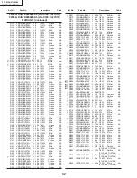
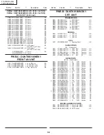
RESISTORS
[M-Ox.··· Metal Oxide, M-Film··· Metal Film]
RJ1
VRD-MN2BE000J
J 0
1/8W
Carbon
AA
RJ9
VRD-MN2BE000J
J 0
1/8W
Carbon
AA
RJ10
VRD-MN2BE000J
J 0
1/8W
Carbon
AA
RJ11
VRS-CY1JF000J
J 0
1/16W
M-Ox.
AA
RJ12
VRD-MN2BE000J
J 0
1/8W
Carbon
AA
RJ13
VRD-MN2BE000J
J 0
1/8W
Carbon
AA
RJ14
VRD-MN2BE000J
J 0
1/8W
Carbon
AA
RJ15
VRS-CY1JF000J
J 0
1/16W
M-Ox.
AA
RJ16
VRS-CY1JF000J
J 0
1/16W
M-Ox.
AA
RJ17
VRD-MN2BE000J
J 0
1/8W
Carbon
AA
RJ19
VRD-MN2BE000J
J 0
1/8W
Carbon
AA
RJ20
VRD-MN2BE000J
J 0
1/8W
Carbon
AA
RJ21
VRD-MN2BE000J
J 0
1/8W
Carbon
AA
RJ22
VRD-MN2BE000J
J 0
1/8W
Carbon
AA
RJ25
VRD-MN2BE000J
J 0
1/8W
Carbon
AA
RJ26
VRS-CY1JF000J
J 0
1/16W
M-Ox.
AA
RJ28
VRD-MN2BE000J
J 0
1/8W
Carbon
AA
RJ29
VRD-MN2BE000J
J 0
1/8W
Carbon
AA
RJ30
VRS-CY1JF000J
J 0
1/16W
M-Ox.
AA
RJ31
VRS-CY1JF000J
J 0
1/16W
M-Ox.
AA
RJ32
VRS-CY1JF000J
J 0
1/16W
M-Ox.
AA
RJ35
VRS-CY1JF000J
J 0
1/16W
M-Ox.
AA
RJ36
VRS-CY1JF000J
J 0
1/16W
M-Ox.
AA
RJ37
VRS-CY1JF000J
J 0
1/16W
M-Ox.
AA
RJ38
VRS-CY1JF000J
J 0
1/16W
M-Ox.
AA
RJ39
VRD-MN2BE000J
J 0
1/8W
Carbon
AA
RJ40
VRD-MN2BE000J
J 0
1/8W
Carbon
AA
Summary of Contents for 27L-S100
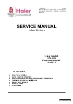
Page 6: ...6 27L S100 27L S180 CL27S10 CL27S18 LOCATION OF USER S CONTROL 27L S100 CL27S10 ...
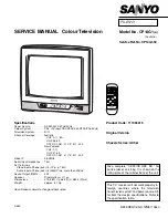
Page 7: ...7 27L S100 27L S180 CL27S10 CL27S18 LOCATION OF USER S CONTROL Continued 27L S180 CL27S18 ...
Page 19: ...19 27L S100 27L S180 CL27S10 CL27S18 17 16 19 18 15 14 13 12 11 10 ...
Page 21: ...21 27L S100 27L S180 CL27S10 CL27S18 17 16 19 18 15 14 13 12 11 10 ...
Page 23: ...23 27L S100 27L S180 CL27S10 CL27S18 17 16 19 18 15 14 13 12 11 10 ...
Page 25: ...25 27L S100 27L S180 CL27S10 CL27S18 17 16 19 18 15 14 13 12 11 10 ...