17
29K-FD5RU
29K-FG5RU
17-1
17-2
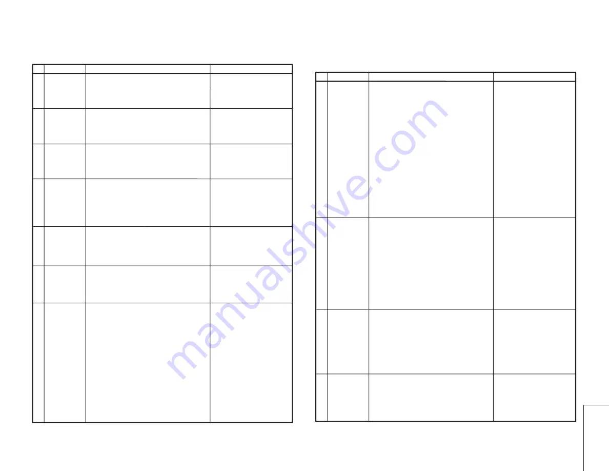
FUNCTION OPERATION CHECKING (VIDEO AND AUDIO)
No. Adjustment point
Adjustment conditions/procedure
Waveform or remarks
CONTRAST
key
1. Receive "Monoscope Pattern" signal.
2. Press to MENU mode, then Select Picture Mode
and set to select CONTRAST.
3. Press Volume Up/Down key to check whether the
CONTRAST effect is OK or not.
1
1. Receive "Colour Bar" signal
.
2. Press to MENU mode, then Select Picture Mode
and set to select COLOUR.
3. Press Volume Up/Down key to check whether
the COLOUR effect is OK or not.
2
COLOUR key
BRIGHTNESS
key
1. Receive "Monoscope Pattern" signal.
2. Press to MENU mode, then Select Picture Mode
and set to select BRIGHTNESS.
3. Press Volume Up/Down key to check whether
the BRIGHTNESS effect is OK or not.
3
TINT key
1. Receive the "NTSC Colour Bar" signal thru AV in.
2. Press to MENU mode, then Select Picture Mode
and set to select TINT.
3. Press Volume Up/Down key to check TINT, UP
for GREEN direction and DOWN for RED direc-
tion whether is OK or not.
4
SHARPNESS
Key
1. Receive "Monoscope Pattern" signal.
2. Press to MENU mode, then Select Picture Mode
and set to select SHARPNESS.
3. Press Volume Up/Down key to check whether
the SHARPNESS effect is OK or not.
5
WHITE TEMP
1. Receive "Monoscope Pattern" signal.
2. Set FUNCTION to select WHITE TEMP.
3. Press Volume Up/Down key to check WHITE
TEMP Option, STANDARD:
NORMAL SETTING, WARM for more REDDISH
direction changing, COOL for more BLUISH di-
rection changing.
NORMAL Key
7
1. Once in PICTURE Mode, and the NORMAL key
is pressed, all the settings will be present to nor-
mal setting.
(Normal setting value for every mode, refer to
Table 2.2 on page 6-1).
Notes:If nothing is display
mean contrast, colour, bright,
tint, sharpness are all in nor-
mal setting.
6
!
"#$%& # &#'
(
)*) +
! "!# $%
! &! !%
"!#
!!' ! &! !
(
! "!# $
! &! !%
"!#
!!' ! &! !
) *+ ,,)-
! "!# $ +,,)
! &! !
*+ ,,)- "!#
!!' ! &! !
, *+ ,,).)/0 -
' 1 !
"!# $ +,,).)/0
! &! ! *+
,,).)/0- "!# !!' !
&! !
,
)
)*) +
-
*%2.3- *+2
- ! .4 5 !'# !'%
' ! &! ! 2.3 #
!'# !'' ! " ' &! !%
( *%5- *+2 %
- ! .4 2.3 !'# !''
! &! ! 5 #
!'# !'' ! " ' &! !
) *%.4- *+2
- ! 5 2.3 !'# !'%
' ! &! ! .4 #
!'# !'' ! " ' &! !%
& +2 ,6678
669 25+
±
/678 2:
( $"'" !'" # # !
!'' & ,6678 !'# # ! !'# !' ;!"
./
; < !; 727+
;!!&
$ 61%
) +
( ' ' !'" !! ! "$"'" "
' !'# # ;!"
' ' !
) !'# "' ;;
, = ' !'# !; 1 ! ""'"
..
Summary of Contents for 29K-FD5RU
Page 24: ...24 29K FD5RU 29K FG5RU CHASSIS LAYOUT 29K FD5RU ...
Page 25: ...25 29K FD5RU 29K FG5RU CHASSIS LAYOUT 29K FG5RU ...
Page 26: ...26 29K FD5RU 29K FG5RU BLOCK DIAGRAMS 29K FD5RU ...
Page 27: ...27 29K FD5RU 29K FG5RU ...
Page 28: ...28 29K FD5RU 29K FG5RU BLOCK DIAGRAMS 29K FG5RU ...
Page 29: ...29 29K FD5RU 29K FG5RU ...
Page 32: ...32 29K FD5RU 29K FG5RU 1 2 3 4 5 6 7 8 9 10 A B C D E F G H I J SCHEMATIC DIAGRAM CRT UNIT ...
Page 33: ...33 29K FD5RU 29K FG5RU 1 2 3 4 5 6 7 8 9 10 A B C D E F G H I J PIP UNIT 29K FD5RU ONLY ...
Page 34: ...34 29K FD5RU 29K FG5RU 1 2 3 4 5 6 7 8 9 10 A B C D E F G H I J MAIN UNIT 29K FD5RU ...
Page 35: ...35 29K FD5RU 29K FG5RU 10 11 12 13 14 15 16 17 18 19 ...
Page 36: ...36 29K FD5RU 29K FG5RU 1 2 3 4 5 6 7 8 9 10 A B C D E F G H I J MAIN UNIT 29K FG5RU ...
Page 37: ...37 29K FD5RU 29K FG5RU 10 11 12 13 14 15 16 17 18 19 ...
Page 38: ...38 29K FD5RU 29K FG5RU 1 2 3 4 5 6 7 8 9 10 A B C D E F G H I J FRONT UNIT ...
Page 39: ...39 29K FD5RU 29K FG5RU 10 11 12 13 14 15 16 17 18 19 ...


