29L-FG1L
3 – 20
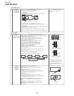
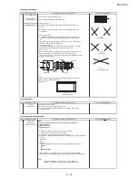
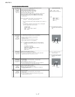
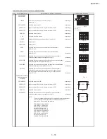
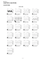
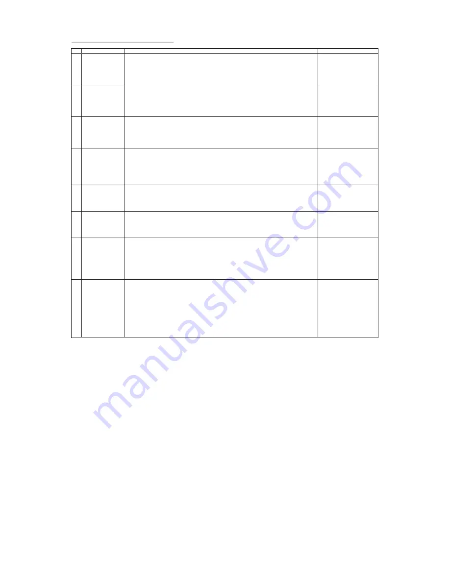
FUNCTION OPERATION CHECKING (1) (VIDEO & AUDIO)
NO
ADJUSTMENT POINT
ADJUSTMENT CONDITION / PROCEDURE
WAVEFORM OR REMARKS
1
CONTRAST Key
(1) Receive "Monoscope Pattern" signal.
(2) Press to Menu mode, then select Picture Mode and set to select CONTRAST.
(3) Press Volume Up/Down key to check whether the CONTRAST effect is OK or not.
2
COLOUR Key
(1) Receive "Colour Bar" signal.
(2) Press to Menu mode, then select Picture Mode and set to select COLOUR.
(3) Press Volume Up/Down key to check whether the COLOUR effect is OK or not.
3
BRIGHTNESS Key
(1) Receive "Monoscope Pattern" signal.
(2) Press to Menu mode, then select Picture Mode and set to select BRIGHTNESS.
(3) Press Volume Up/Down key to check whether the BRIGHTNESS effect is OK
or not.
4
TINT Key
(1) Receive the "NTSC Colour Bar" signal thru AV in.
(2) Press to Menu mode, then select Picture Mode and select TINT.
(3) Press Volume Up/Down key to check TINT, UP for GREEN direction and
DOWN for RED direction whether is OK or not.
5
SHARPNESS Key
(1) Receive "Monoscope Pattern" signal.
(2) Press to Menu mode, then select Picture Mode and set to select SHARPNESS.
(3) Press Volume Up/Down key to check whether the SHARPNESS effect is OK or NOT.
6
NORMAL KEY
(1) Once in PICTURE Mode,and the NORMAL key is pressed,
Note :
all the settings will be present to normal setting.
If nothing is display mean contrast,
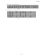
(Normal setting value for every mode, refer Table 2.2 on page 20).
colour, bright, tint, sharpness are
all in normal setting.
7
WHITE TEMP
(1) Receive "Monoscope Pattern" signal.
(2) Set FUNCTION to select WHITE TEMP.
(3) Press Volume Up/Down key to check WHITE TEMP Option, STANDARD:
NORMAL SETTING, WARM for more REDDISH direction changing, COOL for
more BLUISH direction changing.
8
NOISE MUTE
(1) Receive "US10 Half Color Bar" signal.
CHECKING
(2) Turn up the volume control to maximum, make sure the sound is
heard from the speakers. Then put the unit in no signal state.
(3) Check the sound mute is effective.
(4) Finally turn sound level of CTV to minimum.
Summary of Contents for 29L-FG1L
Page 35: ...29L FG1L 8 2 ...
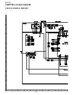
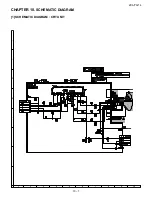
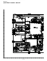
Page 38: ...29L FG1L 10 2 2 SCHEMATIC DIAGRAM MAIN UNIT ...
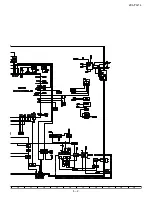
Page 39: ...29L FG1L 10 3 ...
Page 41: ...29L FG1L 11 2 ...
Page 42: ...29L FG1L 11 3 2 MAIN UNIT CHIP PARTS SIDE ...
Page 43: ...29L FG1L 11 4 ...
Page 44: ...29L FG1L 11 5 2 PWB B CRT UNIT ...
Page 61: ...29L FG1L 17 ...

