


29L-FG1L
4 – 1
TV
29L-FG1L
Service Manual
29L-FG1L
Market
E
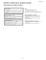
CHAPTER 4.
TROUBLE SHOOTING FLOWCHART
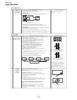
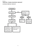
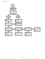
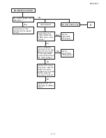
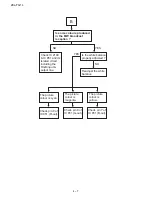
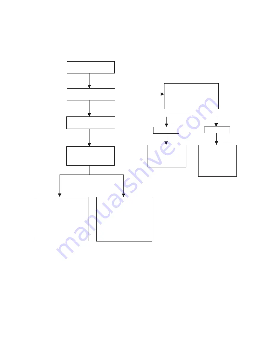
[1] TROUBLE SHOOTING FLOWCHART
NO RASTER
LED COLOUR ?
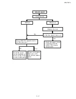
Power on by R/C
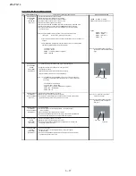
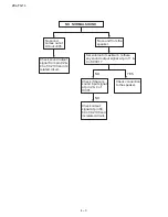
Check protector
circuit and pin 106 &
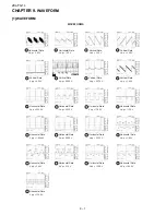
107 (waveform no.3 &
4) of IC 2100. Also
check the waveform
no.7 of IC501 at pin 5
and its related parts.
Does horizontal
circuit momentary
oscillate ?
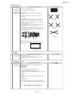
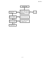
Check CRT connector
(KY), (H) bias.
(Heater voltage,120 V,
210 V line)
Abnormal
Check R,G,B
input and output
of IC 851.
Check the
Heater voltage,
120V and 210V
line from the
main PWB side.
RED
GREEN
RED
Yes
No
Normal
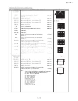
Check 3.3 V & 1.8 V
supplies of IC 2100.
Check oscillation of
crystal X2001.
Summary of Contents for 29L-FG1L
Page 35: ...29L FG1L 8 2 ...
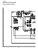
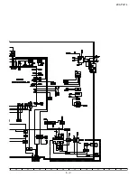
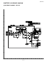
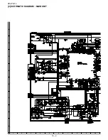
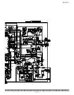
Page 38: ...29L FG1L 10 2 2 SCHEMATIC DIAGRAM MAIN UNIT ...
Page 39: ...29L FG1L 10 3 ...
Page 41: ...29L FG1L 11 2 ...
Page 42: ...29L FG1L 11 3 2 MAIN UNIT CHIP PARTS SIDE ...
Page 43: ...29L FG1L 11 4 ...
Page 44: ...29L FG1L 11 5 2 PWB B CRT UNIT ...
Page 61: ...29L FG1L 17 ...


