5
32SF670
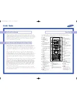
LOCATION OF USER'S CONTROL
Front Panel
POWER
MENU
– VOL +
CH
PULL-OPEN
POWER
MENU
– VOL +
CH
POWER
Press
→
On.
Press again
→
Off.
REMOTE CONTROL
SENSOR
MENU
Press
→
Accesses MAIN MENU.
Press again
→
Exits MAIN MENU.
VOLUME UP/DOWN
(
k
) Increases sound.
(
l
) Decreases sound.
CHANNEL UP/DOWN
(
a
) Selects next higher channel.
(
s
) Selects next lower channel.
VIDEO/AUDIO IN 2
TERMINALS
(INSIDE DOOR)
Note:
• The TV set and remote control illustrations and the on-screen displays in this manual may differ from
their actual appearance.
POWER
Press
→
On.
Press again
→
Off.
REMOTE KEYPAD (0 – 9)
Sets the channel.
RETURN
Returns to the previous screen.
a
/
b
/
c
/
d
Press to select a desired item on
the screen or adjust a selected
item.
EDIT
To enter Personal Preference setting
screen/to exit from Personal
Preference setting screen.
CC
Switches between Closed Caption
service type.
•
(DOT)
Sets the channel.
PERSONAL PREFERENCE
With the Personal Preference buttons,
you can program your favorite
programs by using the 4 categories A,
B, C and D. The channels can be
accessed quickly by using these
buttons.
DISPLAY
To display receiving channel
information.
MUTE
Press
→
Mutes sound.
Press again
→
Restores sound.
FLASHBACK
Returns to previous channel.
VOLUME UP/DOWN
(VOL
k
) Increases sound.
(VOL
l
) Decreases sound.
MENU
Press
→
Accesses MAIN MENU.
Press again
→
Exits MAIN MENU.
GUIDE
Display the programme list.
Infrared Transmitter Window
INPUT
Press
→
Switches to external video
INPUT 1 mode.
Press twice
→
Switches to external
video INPUT 2 mode.
Press 3 times
→
Switches to external
video INPUT 3 mode or
COMPONENT mode.
Press 4 times
→
Switches back to
the original TV mode.
ENTER
Sets the channel.
FLASHBACK
Switches between Screen Format
mode.
AUDIO
Switches between the audio
service type.
CHANNEL UP/DOWN
(CH
r
) Selects next higher channel.
(CH
s
) Selects next lower channel.
Basic Remote Control Functions
Summary of Contents for 32SF670
Page 19: ...19 32SF670 M E M O ...
Page 20: ...20 32SF670 CHASSIS LAYOUT ...
Page 21: ...21 32SF670 BLOCK DIAGRAM ...
Page 23: ...23 8 7 10 9 6 5 4 3 2 1 A B C D E F G H 32SF670 SCHEMATIC DIAGRAM CRT Unit ...
Page 24: ...24 8 7 10 9 6 5 4 3 2 1 A B C D E F G H 32SF670 SCHEMATIC DIAGRAM MAIN 1 Unit ...
Page 25: ...25 17 16 19 18 15 14 13 12 11 10 32SF670 ...
Page 26: ...26 8 7 10 9 6 5 4 3 2 1 A B C D E F G H 32SF670 SCHEMATIC DIAGRAM MAIN 2 Unit ...
Page 27: ...27 17 16 19 18 15 14 13 12 11 10 32SF670 ...
Page 28: ...28 8 7 10 9 6 5 4 3 2 1 A B C D E F G H 32SF670 SCHEMATIC DIAGRAM 2 LINE Y C Unit ...
Page 29: ...29 17 16 19 18 15 14 13 12 11 10 32SF670 ...
Page 30: ...30 8 7 10 9 6 5 4 3 2 1 A B C D E F G H 32SF670 SCHEMATIC DIAGRAM CONTROL Unit ...
Page 31: ...31 17 16 19 18 15 14 13 12 11 10 32SF670 ...
Page 33: ...33 17 16 19 18 15 14 13 12 11 10 32SF670 ...
Page 34: ...34 8 7 10 9 6 5 4 3 2 1 A B C D E F G H 32SF670 PWB A MAIN Unit Components side ...
Page 35: ...35 17 16 19 18 15 14 13 12 11 10 32SF670 ...
Page 37: ...37 8 7 10 9 6 5 4 3 2 1 A B C D E F G H 32SF670 PWB F CONTROL Unit Wiring Side ...


