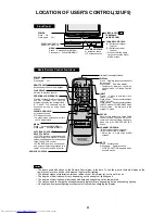
Front Panel
1
2
3
4
5
6
7
8
9
0
100
POWER
TV
MENU
MUTE
PAUSE
FLASHBACK
DISPLAY
INPUT
TV • CATV • VCR • DVD
STOP
REC
REW
PLAY
FF
CH/SKIP
VOL
—
CH
CH
VOL
+
ENTER
A
B
C
D
PERSONAL PREFERENCE
DVD
VCR
CATV
TV
DVD
VCR
Basic Remote Control Functions
Infrared Transmitter Window
DISPLAY
Press
Displays receiving channel for
four seconds.
Press again
Removes display.
• Temporarily displays receiving
channel when in Closed Caption
mode.
INPUT
Press
Switch to external video
INPUT 1 mode.
Press 2 times Switch to external video
INPUT 2 mode.
Press 3 times Switch to external video
INPUT 3 mode or COMPONENT mode.
Press 4 times
Switch back to the
original TV mode.
ENTER
Used in some instances where a Cable
Converter Box requires an “enter”
command after selecting channels,
when using the REMOTE KEYPAD
button.
CHANNEL UP/DOWN
(
8
) Selects next higher channel.
(
9
) Selects next lower channel.
• Moves the “
a
” mark of the MENU
screens.
MUTE
Press Mutes sound.
Press again
Restores sound.
• CLOSED CAPTION appears when
sound is muted.
POWER
Press
On.
Press again
Off.
REMOTE KEYPAD
Accesses any channel from keypad.
FLASHBACK
Returns to previous channel.
PERSONAL PREFERENCE
With the Personal Preference buttons,
you can program your favorite
programs by using the 4 categories A,
B, C and D. The channels can be
accessed quickly by using these
buttons.
VOLUME UP/DOWN
(+) Increases sound.
(–) Decreases sound.
• In menu mode, changes or selects
the TV adjustments.
MENU
Press Accesses MAIN MENU.
Press again Exits MAIN MENU.
CATV/DVD-TV/VCR MODE
SELECT SWITCH
In TV/VCR position, sends power and
channel select commands (Channel
up/down and Random Access buttons)
to the TV and VCR control.
In CATV/DVD position, sends power
and channel select commands to a
cable TV converter and DVD control.
DVD/VCR CONTROL
Note:
• The above shaded buttons on the Remote Control glow in the dark. To use the glow-in-the-dark display on the
remote control, place it under a fluorescent light or other lighting.
• The phosphorescent material contains no radioactive or toxic mater ial, so it is safe to use.
• The degree of illumination will var y depending on the strength of lighting used.
• The degree of illumination will decrease with time and depending on the temperature.
• The time needed to charge the phosphorescent display will vary depending on the surrounding lighting.
• Sunlight and fluorescent lighting are the most effective when charging the display.
POWER
MENU
– VOL +
CH
PULL-OPEN
POWER
MENU
– VOL +
CH
POWER
Press
On.
Press again
Off.
CHANNEL UP/DOWN
(
8
) Selects next higher
channel.
(
9
) Selects next lower
channel.
• Press both at the same
time to access the MAIN
MENU screen.
IN 2
VIDEO/AUDIO
TERMINALS
(INSIDE DOOR)
SENSOR AREA FOR
REMOTE CONTROL
VOLUME UP/DOWN
(+) Increases sound.
(–) Decreases sound.
MENU
Press
Accesses MAIN MENU.
Press again
Exits MAIN MENU.
LOCATION OF USER'S CONTROL(
32UF5
)
4
Summary of Contents for 32UF5
Page 13: ...13 CHASSIS LAYOUT 32UF5 32UF5 ...
Page 14: ...14 BLOCK DIAGRAM 32UF5 4001 4001 4001 4001 32UF5 ...
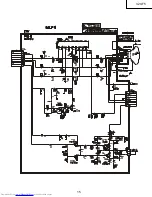
Page 15: ...15 32UF5 ...
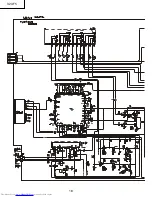
Page 16: ...16 32UF5 ...
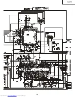
Page 17: ...17 32UF5 ...
Page 18: ...18 32UF5 ...
Page 19: ...19 32UF5 ...
Page 20: ...20 32UF5 ...
Page 21: ...21 32UF5 ...
Page 22: ...22 32UF5 ...
Page 23: ...23 32UF5 ...
Page 24: ...24 32UF5 ...
Page 25: ...25 32UF5 ...
Page 27: ...27 6 5 4 3 2 1 A B C D E F G H PWB A MAIN Unit Chip Parts Side 32UF5 ...
Page 29: ...29 6 5 4 3 2 1 A B C D E F G H PWB H DF MODULE Unit Wiring Side 32UF5 ...
Page 30: ...30 6 5 4 3 2 1 A B C D E F G H PWB F CONTROL Unit 32F631 ONLY Wiring Side 32UF5 ...

