background image

Unplug the AC power lead from the AC socket before con-

necting or disconnecting any component.

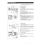
AM loop aerial

15 m (49 feet)

Aerial connection

(1) Supplied FM aerial

Connect the FM aerial wire to the FM 75  OHMS terminal and
orient the FM aerial wire in the direction where the strongest
signal can be received.

(2) Supplied AM loop aerial

Connect the AM loop aerial wire to the AM and GND terminals.
Position the AM loop aerial for optimum reception.
Place the AM loop aerial on a shelf, etc., or attach it to a stand
or wall with screws (not supplied).

Notes:

 When static is still heard even after adjusting the position of

the AM loop aerial, try reversing the wires.

 Do not place the AM loop aerial and the FM aerial wire on

the unit. It may result in noise generation, since the unit is
equipped with digital electronics.

Place the AM loop aerial and the FM aerial wire away from

the unit for better reception.

 If the AM loop aerial and the FM aerial wire are placed near

the AC power lead, it may cause interference.

(3) External FM aerial

To connect a 75 ohm, coaxial cable aerial, use the terminals
marked FM 75 OHMS and GND.

To connect the external aerial to the unit, it is recommended that
a 75 ohm coaxial cable be used. Its shielded construction resists

most types of electrical interference that can cause reception
noise.

Consult your SHARP audio dealer for suggestions on the type
of aerial best suited for your area.

Note:

When an external FM aerial is used, 

 the supplied FM

aerial wire from the FM 75 OHMS terminal.

(4) 

External AM aerial

Use an external AM aerial (not supplied) if you need better re-
ception.
Consult your dealer.

Note:

When using an external AM aerial, be sure to keep both wires
of the AM loop aerial connected.

3

Summary of Contents for AE-X127J

Page 1: ...ERATION MANUAL INDOOR UNIT OUTDOOR UNIT A Xl 275 AE X127J Thank you for purchasing this Sharp product Please read this manual carefully before operating the air conditioner and keep this manual and the Installation Manual as handy references ...

Page 2: ...er for infants children elderly bedridden or disabled people make sure the room temperature is suitable for those in the room Always use a fuse with the correct current rating Use only the manufacturer specified power cord parts code QACC A234JBEO for its replacement Replacement should be conducted by a service centre approved by Sharp A 1 This unit is designed for human comfort Do not use for app...

Page 3: ...ing l A hissing sound may be heard originating from the indoor unit during de icing l After de icing is completed the unit automatically resumes operation in the HEAT mode HEATING EFFICIENCY l The unit employs a heat pump that draws heat from the outside air and releases it into the room The outside air temperature therefore greatly affects the heating efficiency l If the outside temperature is un...

Page 4: ... Window AUX Button OUTDOOR UNIT Inlet Air Indicator Panel Hinged Front Panel Operation Panel Air Filters Power Supply Cord 0 Vertical Adjustment Louvre Horizontal Adjustment Louvres Outlet Air Remote Control Inlet Air Refrigerant Tubes and Intercon necting Cord 0 Drainage Hose Outlet Air NOTE Actual units might vary slightly from those shown above 3 ...

Page 5: ...mer TIME ADVANCE Button CLOCK Button Indicates BATTERY COMPARTMENT is below this mark TIME REVERSE Button L C D REMOTE CONTROL DISPLAY 0 THERMOSTAT SETTING FOR AUTO AND DRY MODES TEMPERATURE SYMBOL TRANSMITTING SYMBOL I MODE SYMBOLS Q AUTO DRY HEAT FAN ONLY c COOL TEMPERATURE INDICATOR I FULL POWER OPERATION MODE SYMBOL FAN SPEED SYMBOLS P AUTO LOW HIGH 0 SOFT 0 TIMER ON INDICATOR CLOCK Indicates ...

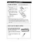
Page 6: ...he batteries always use two new ones of the same type l If the remote control does not operate normally after replacing the batteries take out the batteries and replace them again after 30 seconds l If you will not be using the unit for a long time remove the batteries from the remote control HOW TO USE THE REMOTE CONTROL Point the remote control towards the indoor unit s receiver window and press...

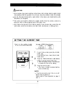
Page 7: ...r a heater Also protect the unit and remote control from moisture and shock which can discolour or damaae them SETTING THE CURRENT TIME There are two setting modes 12 hour clock and 24 hour clock Example 5 o clock in the afternoon d 1 To set 12 hour clock press the CLOCK button once To set 24 hour clock press the CLOCK 3 button twice 2 Press the TIME ADVANCE or REVERSE 1 buttons to set the current...

Page 8: ...perature In the AUTO and DRY 2 C higher mode the indicator bars 1 C higher represent changes in v 1 C lower temperature v 2 C lower In the manual HEAT and COOL mode the tem perature can be set within the range of 18 to 32 C In the FAN ONLY mode the temperature cannot be set 7 Press the FAN button to set the desired fan speed AUTO HIGH LOW SOFT pP O 7 l In the DRY mode the fan speed cannot be chang...

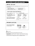
Page 9: ... and the louvre will stop Adjustment range COOL and DRY mode HEAT and FAN ONLY mode The range is narrower to prevent condensation from forming The range is wider for in creased air circulation Hold the horizontal adjustment louvres as shown and adjust the air flow direction HORIZONTAL AIR FLOW I il n 1 CAUTION 0 Never attempt to adjust the vertical adjustment louvres manually l Manual adjustment o...

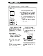
Page 10: ...FF mode is set the room temperature is automatically ad justed to prevent the room from becom ing too hot or too cold while you sleep Auto sleep function COOL DRY MODE l One hour after the timer operation has begun the temperature rises 1 C higher than the thermostat setting HEAT MODE l One hour after the timer operation has begun the temperature drops 3 C lower than the thermostat setting Press t...

Page 11: ...ature by the programmed time Awaking function COMBINED USE OF ON AND OFF TIMERS You can combine the use of the ON and OFF timers Example Stop operation at 1 I 00 p m and resume operation using the same settings to obtain the desired room temperature by 7 00 a m 1 Set the TIMER OFF to 1 I 00 p m during opera tion 2 Set the TIMER ON to 7 00 a m The arrows V orlr between the TIMER ON indicator and th...

Page 12: ...mode dur ing the DRY or the FAN ONLY mode l You cannot set the temperature during the FULL POWER operation The fan speed is adjustable When the ONE HOUR TIMER is set the unit will operate for one hour after setting 1 Press the ONE HOUR TIMER button l 1 H will be displayed on the remote con trol l The unit will operate for one hour 2 To turn off the unit within an hour press the Atton ON OFF bl l T...

Page 13: ...it will turn off Be sure to unplug the power cord from the wall outlet or turn off the circuit breaker before performing any maintenance CLEANING THE FILTERS The air filters should be cleaned every two weeks 1 TURN OFF THE UNIT 2 REMOVE THE FILTERS 1 Lift up the front panel of the indoor unit 2 Push the air filters up slightly to unlock them 3 Pull the air filters down to remove them 3 CLEAN THE F...

Page 14: ...support with each hand Carefully push in the supports until the hooks fit the inside holes CLEANING THE UNIT AND THE REMOTE CONTROL l Wipe them with a soft cloth l Do not directly splash or pour water on them It could result in electrical shock or damage to them l Do not use hot water thinner abrasive powders or strong solvents POST SEASON CHECK r PRE SEASON CHECK 1 2 3 Operate the unit in the FAN...

Page 15: ... to be malfunctioning check the following points before calling for service I IF THE UNIT FAILS TO OPERATE Check to see if the circuit breaker has tripped or the fuse has blown IF THE UNIT FAILS TO COOL OR HEAT THE ROOM EFFECTIVELY 1 Check the filters If they re dirty clean them Make sure windows and doors are closed tightly Check the outdoor unit to make sure nothing is blocking the air inlet or ...

Page 16: ...4 SHARP CORPORATION OSAKA JAPAN PRINTED IN JAPAN TINSEAI 67JBR0 7D0 ...

Page 17: ...CD C415W mini component system consisting of CD C41 5W mini component system CP C415 speaker system grj DIGITAL AUDIO ...

Page 18: ...ers in Australia 0 Copyright may exist in material you wish to record Copying or broadcasting such material without permission of the relevant licensees or owners of the copyright is prohibited by law SHARP is not in a position to authorise the copying or broadcasting of copyright materials and nothing in this OPERATION MANUAL should be implied as giving that authority For other countries 0 Audio ...

Page 19: ...ion and various other factors It is advisable to avoid exposure to high volume levels which occur whilst turning the unit on with the volume control set ting up high or whilst continually listening at high volumes n Condensation Sudden temperature changes storage or operation in an extremely humid environment may cause condensation in side the cabinet CD pickup tape heads etc or on the transmitter...

Page 20: ...ince the unit is equipped with digital electronics Place the AM loop aerial and the FM aerial wire away from the unit for better reception 0 If the AM loop aerial and the FM aerial wire are placed near the AC power lead it may cause interference 3 External FM aerial To connect a 75 ohm coaxial cable aerial use the terminals marked FM 75 OHMS and GND To connect the external aerial to the unit it is...

Page 21: ...ar panel to AM tuning interval span of your area To change the tuning zone 1 Set the ON STAND BY switch to STAND BY 2 Set the SPAN SELECTOR switch as desired 0 Set the SPAN SELECTOR switch to 50 9 for 9 kHz AM in terval 50 kHz FM interval and 100 l 0 for 10 kHz AM in terval 100 kHz FM interval 3 Press and hold down the VOLUME v button the W W button and the ON STAND BY switch all at the same time ...

Page 22: ...ncorrectly may cause the unit to mal function Precautions for battery use 0 Insert the batteries according to the direction indicated in the battery compartment 0 Replace all old batteries with new ones at the same time 0 Do not mix old and new batteries 0 Remove the batteries if they are weak or if the unit is not in use for long periods to prevent potential damage due to battery leakage Caution ...

Page 23: ...yback 2 Select the desired sound mode When the 3D SURROUND 30 SURROUND MODE button is pressed the current mode setting will be displayed To change to a different mode press the 3D SURROUND 30 SURROUND MODE button repeatedly 0 To listen to music in the 3D SURROUND mode select either SURROUND MODE 1 or SURROUND MODE 2 SRS 0 will appear OFF SURROUND MODE l SURROUND MODE 2 t I Note 0 The 30 SURROUND e...

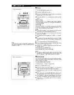
Page 24: ...time in 5 minute intervals The hour setting will not advance even if minutes advance from 59 to 00 Press the MEMORY SET button The clock starts operating from 0 seconds Seconds are not displayed Note l In the event of a power failure or when the AC power lead is disconnected the clock display will go out When the AC power supply is restored the clock display will flash on and off to indicate the t...

Page 25: ...sc tray Be sure to place 8 cm 3 CD s in the middle of the disc trays Caution Do not stack CDs in the tray This can damage the player and the CDs 5 6 a When loading a third disc press the DISC SKIP button to turn the disc tray then place the CD in the open position Press the OPEN CLOSE button to close the disc tray The total number of tracks and the total playing time for one disc will be displayed...

Page 26: ...ttons l 3 is pressed during playback play back of the selected disc will begin auto matically It is not necessary to press the c button To listen to the track being played again Press the H1 button for less than 0 5 seconds during playback To move to the beginning of the next track Press the H button for less than 0 5 seconds during playback 0 To skip a number of tracks at one time press the w or ...

Page 27: ...tions Remote control operation Press the CLEAR button whilst the disc is stopped 0 Each time the button is pressed one track will be cleared beginning with the last track programmed Notes Opening the disc tray automatically cancels the programmed sequence Even if you set the ON STAND BY switch to STAND BY or the function is changed from CD to some other function the programmed selections will not ...

Page 28: ...so that the ST indicator on the display lights UP a will appear when an FM broadcast is in stereo If the FM reception is weak press the TUNER BAND button so that the ST indicator goes out Although the reception changes to monaural the sound becomes clearer To switch the unit off after use Set the ON STAND BY switch to STAND BY Note 0 The memory recalls the last station received even after changing...

Page 29: ...p the memory scan at the desired station Note When the preset memory does not have any stations stored in it the preset memory scan will not function 1 6 2 s I I Ilk rL Ail 6 6 2 5 9 HTAPE 1 or TAPE 2 playback 1 Set the ON STAND BY switch to ON 2 Press the TAPE l 2 button 3 Open the cassette door by pushing the area marked PUSH EJECT 4 Load the cassette into the TAPE 1 or TAPE 2 cassette com partm...

Page 30: ...stop recording Press the n button The CD and tape will stop Note 0 When the end of the tape is reached whilst the unit is rec ording the CD player will display the track number which was being played at that time and stop automatically After you turn over the tape and press the REC PAUSE 0 II button and then c button recording will restart from the beginning of the track that was interrupted whils...

Page 31: ...EMORY SET button Press the TUNING TIME v or A button to set the minute at which to start and then press the MEMORY SET button The power will be automatically turned off and the time will be displayed When the preset time is reached the volume will increase gradually until it reaches the volume you were listening to before turning off the unit If you select CD or TAPE during timer playback the powe...

Page 32: ...audio output to this unit and the video output to a television Set the ON STAND BY switch to ON Press the VIDEO AUX button Operate the external unit To record the sound from the external unit perform steps 2 4 of the Recording from the built in radio section on page 13 Note 0 To prevent hum interference do not place this unit near tele vision receivers 15 9 2 34 9 F I JI Before you move this produ...

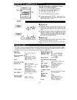
Page 33: ...n and specification changes for product improvement without prior notice The performance specification figures indicated are nominal values of production units There may be some deviations from these values in individual units 0 General Power source AC 11 O l 27 220 230 240 V 50 60 Hz Power consumption 65 W Dimensions Width 270 mm 1 O 5 8 Height 300 mm 1 l 1 3 l 6 Depth 359 5 mm 14 3 l 6 Weight 5 ...

Page 34: ...i TINSEOI 61AWZZ I 4 S H A R P SHARP CORPORATION A9703 SM ...

Reviews: