background image


SERVICE MANUAL

AYXPC18LR

S3011AYXPC8LRT

Parts marked with "

" are important for maintaining the safety of the set. Be sure to replace these parts with specified ones for maintaining the

safety and performance of the set.

This document has been published to be used for
after sales service only.
The contents are subject to change without notice.

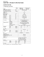
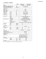
CHAPTER 1. PRODUCT SPECIFICATIONS

[1] SPECIFICATION ...........................................1-1
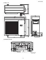
[2] EXTERNAL 

DIMENTIONS ............................1-3
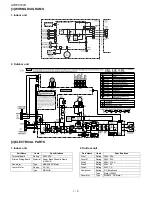
[3] WIRING 

DIAGRAMS .....................................1-5

[4] ELECTRICAL 

PARTS....................................1-5

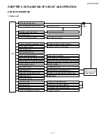
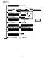
CHAPTER 2. EXPLANATION OF CIRCUIT AND OP-
ERATION

[1] BLOCK 

DIAGRAMS ......................................2-1

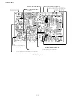
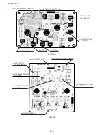
[2]  MICROCOMPUTER CONTROL SYSTEM

........2-3

[3] FUNCTION ....................................................2-8

CHAPTER 3. FUNCTION AND OPERATION OF PRO-
TECTIVE PROCEDURES

[1] TROUBLESHOOTING 

GUIDE ......................3-1

[2] CHART ..........................................................3-2

CHAPTER 4. REFRIGERATION CYCLE

[1] REFRIGERATION 

CYCLE............................. 4-1

[2] PERFORMANCE 

CURVES ........................... 4-2

[3]  REFRIGERANT PIPE INSTALLATION 

WORKS ......................................................... 4-3

CHAPTER 5. DISASSEMBLING PROCEDURE

[1] INDOOR 

UNIT ............................................... 5-1

[2] OUTDOOR 

UNIT ........................................... 5-5

Parts Guide

TopPage

CONTENTS

MODELS

SPLIT TYPE
ROOM AIR CONDITIONER

INDOOR UNIT

AY-XPC18LR

AY-XP24LR

OUTDOOR UNIT

AE-X18LR

AE-X24LR

Summary of Contents for AE-X18LR

Page 1: ...DIMENTIONS 1 3 3 WIRING DIAGRAMS 1 5 4 ELECTRICAL PARTS 1 5 CHAPTER 2 EXPLANATION OF CIRCUIT AND OP ERATION 1 BLOCK DIAGRAMS 2 1 2 MICROCOMPUTER CONTROL SYSTEM 2 3 3 FUNCTION 2 8 CHAPTER 3 FUNCTION AND OPERATION OF PRO TECTIVE PROCEDURES 1 TROUBLESHOOTING GUIDE 3 1 2 CHART 3 2 CHAPTER 4 REFRIGERATION CYCLE 1 REFRIGERATION CYCLE 4 1 2 PERFORMANCE CURVES 4 2 3 REFRIGERANT PIPE INSTALLATION WORKS 4 3...

Page 2: ... rotary type Model C 6RVN103H0Q Oil charge FREOALALF68SZ 600cc Refrigerant system Evaporator Louver Fin and Grooved tube type Condenser Corrugate Fin and Grooved tube type Control Expansion valve Refrigerant R410A 1100g De lce system Micro computer controled reversed systems Noise level cooling High dB A 43 49 Low dB A 39 Soft dB A 33 Fan system Drive Direct drive Air flow quantity cooling High m3...

Page 3: ...Oil charge FREOALALF68SZ 600cc Refrigerant system Evaporator Louver Fin and Grooved tube type Condenser Corrugate Fin and Grooved tube type Control Expansion valve Refrigerant R410A 1680g De lce system Micro computer controlled reversed systems Noise level cooling High dB A 47 53 Low dB A 42 Soft dB A 35 Fan system Drive Direct drive Air flow quantity cooling High m3 min 18 4 45 6 Low m3 min 14 4 ...

Page 4: ...AYXPC18LR 1 3 2 EXTERNAL DIMENTIONS 1 Indoor unit 222 325 1040 Remote controller 204 57 18 ...

Page 5: ...ension 850 141 211 557 379 395 689 21 710 144 84 920 363 330 12 50 4 5 72 880 80 137 325 50 33 137 42 1040 Unit size 80 A J I F E H I E G F D D J E B A C Center of wall hole Leftward piping Center of wall hole Backward piping Outline of indoor unit ...

Page 6: ...EN YELLOW CONTROL BOX L SUB CONTROL BOARD UNIT CN8 SERIAL SIGNAL CIRCUIT Part Name Items Specifications Terminal Board Rating 300V 25A Printed Wiring Board Material Paper Base Phenolic Resin UL94V 0 Fan motor Type MLB438 DC Motor Louver Motor Rating DC12V Type MP24GA Part Name Items Specifications Fuse1 Rating 250V 20A Fuse101 Rating 250V 20A Fuse3 Rating 250V 3 15A Fuse5 Rating 250V 2A Fuse6 Rati...

Page 7: ...t Switchover circuit Serial I O circuit Compressor relay drive circuit LED drive circuit Auto restart circuit Test run circuit Auxiliary mode Power on circuit Cluster generator drive circuit Indoor fan motor Fan motor pulse detect Flow direction control Wireless remote control operation Audible operation confirmation Room temp thermistor Heat exchanger pipe thermistor Blower temperature fan speed ...

Page 8: ...ignals Outdoor fan 4 way valve Power transistor module Compressor Current transformer Compressor thermistor Heat exchanger pipe thermistor Outdoor temperature thermistor LED Power supply circuit CPU oscillator circuit DC overvoltage detection circuit Outdoor fan drive circuit 4 way valve relay drive circuit Power transistor module drive circuit Serial I O circuit CPU reset circuit Position detecti...

Page 9: ...AYXPC18LR 2 3 2 MICROCOMPUTER CONTROL SYSTEM 1 Indoor unit ...

Page 10: ... EVAPORATOR AND TERMINAL BOARD E TO TERMINAL BOARD TOP N FROM TERMINAL BOARD TOP I FROM FAN MOTOR FROM CLUSTER GENERATOR FROM THERMISTOR FROM LOUVER MOTOR HORIZONTAL FROM TERMINAL BOARD TOP TO TERMINAL BOARD TOP 2 FROM LOUVER MOTOR VERICAL ...

Page 11: ...10KF 1 4W IC1 L1 2 0kF 1 0kF 25V 5V 2 0kF 0 1uF 5V 50V 7 8 9 6 5 4 3 2 1 5V 15V 1 2 3 4 5 6 9 8 7 15V 100uF 100pF 1k 100pF 50V D301 5V 5V 5V 0 1uF 0 033uF 0 1uF 5V 5V 5V CN301 5V 15V 10k C76 0 1uF 25V 25V 25V BCN13 6 8k 25V 0 1uF R76 50V 1000pF 1k R70 JP94 C305 C306 C307 C309 C310 C311 C312 C313 C314 0 1uF 25V 180kF 1 4W 180kF 1 4W Z W Y X V U 4 3 2 1 CN 1 50V 4 7uF 5V C66 0 1u C67 V 10 100u R77 1...

Page 12: ... from PFC COIL from CONTROL BOARD P W B MRY1OUT from CONTROL BOARD P W B BCN13 from CONTROL BOARD P W B T6 from ELECTROLYTIC CAPACITOR C10 from ELECTROLYTIC CAPACITOR C10 from COMPRESSOR TERMINAL W ORANGE from COMPRESSOR TERMINAL V WHITE from COMPRESSOR TERMINAL U RED from CONTROL PWB CN14 from CONTROL PWB BCN1 ...

Page 13: ...RD N POWER SUPPLY from TERMINAL BOARD THERMAL FUSE from TERMINAL BOARD to TERMINAL BOARD 1 to TERMINAL BOARD N from DC FAN MOTOR from 4WAY VALVE from EXPANSION VALVE from THERMISTOR to IPM P W B to PFCM P W B from IPM P W B CN114 from PFCM P W B AC1 from PFCM P W B AC2 from PCONTROL BOX ...

Page 14: ...rating fre quency the compressor stops operating and then restarts after about 180 seconds and the above mentioned control is repeated 6 Outdoor unit overheat prevention control During cooling operation if the temperature of the outdoor unit heat exchanger exceeds the outdoor unit heat exchanger overheat preven tion temperature about 55 C the operating frequency is decreased by about 4 to 15 Hz Th...

Page 15: ...s determined automatically by the room temper ature sensor When a circuit breaker is used to control the ON OFF operation please insert a jumper as described above 15 Self diagnostic malfunction code display 15 1 Indoor unit 1 When a malfunction is confirmed all relays turn off and a flashing operation LED timer LED Plasamacluter LED is displayed to indi cate the type of malfunction When the air c...

Page 16: ...ting automatically deter mined based on the outside air operation The setting value is the same as the set temperature for cooling operation in the auto mode If the room temperature is lower than 26 C when dehumidifying opera tion starts the dehumidifying operation minimizes the lowering of the room temperature 21 FULL POWER Operation In this operation the air conditioner works at the maximum powe...

Page 17: ...d PCB the auto restart function can be disabled 28 Energy Saving Operation 28 1 Cool Dry Operation By pressing ENERGY SAVE button during Cool Dry operation the set temperature will vary with 1 f fluctuation 1 f fluctuation resembles fluc tuation existing in nature and is said that it gives relaxation 1 f Fuzzy Logic By varying the set temperature in 1 C 0 33 C range follow ing 1 f fluctuation the ...

Page 18: ...C Module By adding ON signal to the gate of IGBT from the control IC IGBT turns ON and the collector current Ic flows This current flows from the side of the diode bridge DB to the Choke coil the side of the diode bridge DB through IGBT from the Choke coil L At this time energy is stored in the choke coil L Next when gate signal of IGBT turned OFF IGBT will be turned OFF and the energy stored in L...

Page 19: ...AC voltage of the PFC Module circuit with pin 71 and detecting AC current wave form with pin 72 The microcomputer calculates to do above mentioned controls and outputs the PFC signal ON OFF duty control of 20kHz from pin 89 The PFC signal is input to IN of PFCM and the PFC Module circuit operates 29 4 Output voltage of PFC Module The output DC voltage of the PFC Module circuit changes within the r...

Page 20: ... of self diagnosis result displayed on indoor unit Suction thermistor open circuit error 2 The self diagnosis display function of the outdoor unit indicates the error information by flashing LED1 on the outdoor unit according to the content of self diagnosis The self diagnosis display function of the outdoor unit is active only for about 3 to 10 minutes after self diagnosis is performed during ope...

Page 21: ...nit compres sor thermistor assembly 5 Replace the expansion valve coil expansion valve or outdoor unit control PWB assembly 1 Measure resistance of the heat sink thermistor 1 Replace the heat sink thermistor Inspection location method Remedy Normal Heat exchanger thermistor short circuit error Outdoor tempera ture thermistor short circuit error Suction thermistor short circuit error Compressor hig...

Page 22: ...uit error Suction thermistor open circuit error Discharge thermis tor open circuit error DC overcurrent er ror AC overcurrent er ror AC maximum cur rent error AC current defi ciency error Lighting pattern at the time of timer lamp lighting Off for 5 seconds Operation lamp Cluster lamp Operation lamp Cluster lamp Operation lamp Cluster lamp Operation lamp Cluster lamp Operation lamp Cluster lamp Op...

Page 23: ... IPM terminal resistance values are uniform 3 Check if outdoor main relay MRY1 turns on and voltage of both end of the capacitor C10 has become DC330V 4 No abnormality found in above inspections 1 and 3 5 No abnormality found in above inspections 1 and 4 1 Correct the installation U Red V White W Orange 2 Replace the outdoor unit control PWB assembly 3 Replace the outdoor unit control PWB assembly...

Page 24: ...ire of the indoor unit fan motor for open circuit 3 Check CN8 of the indoor unit fan motor for secure installation 4 No abnormality found in above inspec tions 1 through 3 1 Replace the indoor unit fan motor 2 Replace the indoor unit fan motor 3 Correct the installation of CN8 of the indoor unit fan motor 4 Replace the indoor unit control PWB 1 Error in data read from the indoor unit EEPROM 1 Repl...

Page 25: ...hange thermistor TH2 Orange TH3 Black 25ºC resistance 4 431 k 500K 400K 300K 200K 100K 0 20 0 20 60 80 100 120 3 06K 5 78K 4 17K 2 28K 1 72K 1 8 40K 30K 20K 10K 0 20 0 20 60 40 1 8 Connector CN8A Connector CN8A TH2 Heat exchange thermistor TH3 Outdoor temp thermistor TH4 Suction pipe thermistor TH1 compressor thermistor TH2 TH3 TH4 Temperature ºC Temperature ºC Tester Tester Thermistor To measure ...

Page 26: ...UID Silencer Coil Muffler s 1 4 2 Accumulator Sub Accumu lator Muffler 3 Strainer s Strainer Expansion valve Heating Cooling Outdoor unit Condenser Evaporator Indoor unit Reverse valve Comp ressor Flare coupling Flare coupling 3 way valve GAS 3 way valve LIQUID Silencer Coil C Indoor side Outdoor side Dry bulb Temperature Relative humidity Dry bulb Temperature C Relative humidity Cooling 27 C 47 3...

Page 27: ...p ºC Outlet air temp ºC 4 0 4 2 4 4 4 6 4 8 5 0 5 2 5 4 5 6 5 8 6 0 6 2 20 25 30 35 40 45 50 Cooling capacity kW 1000 1100 1200 1300 1400 1500 1600 1700 20 25 30 35 40 45 50 Input W 10 0 11 0 12 0 13 0 14 0 15 0 16 0 20 25 30 35 40 45 50 Outside air temp ºC Outlet air temp ºC Outside air temp ºC Outside temp ºC 2 4 2 8 3 2 3 6 4 0 4 4 4 8 5 2 5 6 6 0 6 4 10 5 0 5 10 15 Heating capacity kW 1100 120...

Page 28: ...100 2200 2300 2400 2500 20 25 30 35 40 45 50 Input W 10 0 11 0 12 0 13 0 14 0 15 0 16 0 20 25 30 35 40 45 50 Outside air temp ºC Outside air temp ºC Outside temp ºC Outlet air temp ºC 3 0 3 8 4 6 5 4 6 2 7 0 7 8 8 6 10 5 0 5 10 15 Heating capacity kW 1450 1550 1650 1750 1850 1950 2050 2150 10 5 0 5 10 15 Input 32 0 34 0 36 0 38 0 40 0 42 0 44 0 10 5 0 5 10 15 MODEL PIPE SIZE STANDARD PERMISSIBLE L...

Page 29: ...ing the disassembly procedure When reassembling the unit after repair ing be sure to install screws to their original positions The screws used are not the same in specifications such as corrosion resistant treatment tip shape and length After the air conditioner is repaired or parts are replaced measure insulation resistance of the equipment using an insulation resistance meter If the measured re...

Page 30: ...n of an arrow 18000BTU model only Remove a screw fixing the ground wire 18000BTU MODEL 24000BTU MODEL 9 Remove 2 screws fixing the cover 10 Remove a screw fixing the thermistor holder Remove the thermistor holder 11 Disconnect the connector and remove 2 screws fixing the control box assembly 12 Remove the control box assembly 㪟㪦㪦㪢 㪟㪦㪦㪢 㪪㪚㪩㪜㪮 㪚㫆㫅㫋㫉㫆㫃 㪺㫆㫍㪼㫉 㪟㪦㪦㪢 㪟㪦㪦㪢 㪧㪮㪙㩷㪿㫆㫃㪻㪼㫉 Cover Screw Control b...

Page 31: ... side Right side 14 Remove the drain cover from the evaporator 15 Remove 2 screws fixing the evaporator 16 Remove the 2 screws fixing the side coder L 17 Remove 3 screws fixing the side cover R and remove the and remove the evaporator from the cabinet 18 Loose a screw fixing cross flow fan ...

Page 32: ... terminal board 2 Pull the control board unit 3 The louver and related 1 Remove the two screw fixing the louver motor 2 Open the horizontal louver to remove it from the holders 3 Remove the holders 4 Tilt the hooks of vertical louvers inside and pull them up Holder ...

Page 33: ...rew fixing the front panel R and slide the front panel R down then remove it 4 Remove the 5 screws fixing the motor angle T then remove it 5 Remove the 2 screws fixing the angle then remove it 6 Remove the 4 screws fixing the front panel L then remove it Side cover Valve cover Top plate Top plate Front panel R Motor angle T Angle The hook is removed Front panel L 1 2 Front panel L ...

Page 34: ...rminals Fan motor Expansion valve Thermistor NOTE Caution to the position of connectors when reinstalling 10 Remove the 5 screws fixing the controlbox assembly then remove it 11 Remove the 11 screws fixing the side cover R and slide the side cabinet R Cut Control box cover Fan motor Thermistor Coil of reverse valve Coil of expansion valve Thermistor Red U White V Orange W Control Box Assembly Cont...

Page 35: ...above condition and remove the side cabinet R by sliding to sideways 12 Remove the screws fixing the side cabinet L then remove it 13 Remove the 2 screws fixing the bulkhead then remove it 14 Remove the compressor covers 3pcs Side cabinet R Side cabinet R Side cabinet L Remove Remove ...

Page 36: ...d terminal cover 18 Disconnect 3 terminals NOTE Caution to the position of connectors when reinstalling 19 Remove the 1 nut fixing the propeller fan then remove it 20 Remove the 2 screws fixing the motor angle then remove it Thermistor Thermistor Remove Nut Terminal cover Orange C White S Red R Nut Propeller fan ...

Page 37: ...How to disassemble the control box assembly 1 Remove the 4 screws fixing the PWB then remove it 2 Remove the 2 screws fixing the IPM then remove it 3 Remove the 3 screws fixing the PAM 4 Remove the 3 screws fixing the Active coil Cut the fixing band Black lead wire Red lead wire Green lead wire Orange lead wire P W B Unlock the spacer Active coil PAM IPM ...

Page 38: ...AYXPC18LR 5 10 ...

Page 39: ... without notice AYXPC18LR HOW TO ORDER REPLACEMENT PARTS To have your order filled promptly and correctly please furnish the following information 1 MODEL NUMBER 2 REF NO 3 PART NO 4 DESCRIPTION SPLIT TYPE AIR CONDITIONER MODELS INDOOR UNIT AY XPC18LR AY XP24LR OUTDOOR UNIT AE X18LR AE X24LR PartsGuide 1 INDOOR UNIT PARTS 2 ACCESSORY PARTS 3 INDOOR PACKING PARTS 4 OTHER PARTS 5 OUTDOOR UNIT PARTS ...

Page 40: ... 2 2 2 10 2 22 1 29 1 7 2 20 1 10 1 8 1 22 1 54 1 52 1 21 1 12 1 11 1 9 1 16 2 21 4 3 2 13 1 28 1 5 4 7 1 6 1 4 1 36 1 60 2 19 5 1 1 59 2 24 3 7 2 4 1 3 1 1 2 19 3 9 1 13 1 13 1 53 1 21 4 1 14 2 6 3 1 3 4 3 5 3 3 3 2 1 17 2 3 5 2 2 17 2 16 2 25 1 43 2 24 1 58 1 56 1 55 2 7 1 35 1 34 1 41 ...

Page 41: ...bel 24 1 44 TLABCC718JBRZ AK Wiring Diagram 1 52 DWAK B002JBKZ BB FRONT PANEL Assembly 1 53 PSEL E004JBEZ AL SEAL 1 54 RMOT A193JBZZ AZ Louver Motor 1 55 PSEL E003JBEZ AK Seal 1 56 PSEL E199JBEZ AH Insulator 1 58 PSEL E087JBEZ AH Insulator Attach to 1 28 1 59 PCOV B754JBFA AK Cover 18 1 60 PCOV B772JBEZ AK Cover 2 2 PBOX A537JBFA AX Control Box 2 3 CCOV A283JBKZ BB Control Cover Assembly 2 4 LHLD ...

Page 42: ...y for 1800 Btu type accessory kit parts of OUTDOOR UNIT 4 8 XTTS745P30000 AC Tapping Screw 4 9 TINS B246JBRZ AK Installation Manual 18 4 9 TINS B270JBRZ AP Installation Manual 24 4 11 TINSEA639JBRZ AN Operation Manual 4 12 CFIL A087JBKZ BB Purify Filter Assembly 3 INDOOR PACKING PARTS 6 1 SPADBA480JBEZ AP Packing Pad 6 2 SPADBA481JBEZ AP Packing Pad 6 3 SPAKCC839JBEZ BB Packing Case 18 6 3 SPAKCC8...

Page 43: ...ARTS 1 1 CMOTLB426JBEZ CA Fan Motor 1 2 LANGKA253JBPZ AM Fan Motor Angle Sub 1 11 1 10 1 17 1 17 5 1 17 1 1 17 2 1 17 3 1 17 4 1 16 2 1 13 1 36 4 1 14 1 15 1 2 1 37 6 22 1 21 1 5 1 1 5 1 33 1 8 1 3 1 4 1 4 1 1 16 1 1 16 1 37 1 26 1 35 1 27 1 6 1 25 1 20 1 1 6 13 1 7 1 36 2 1 36 1 1 36 1 36 3 1 18 1 12 1 34 ...

Page 44: ... Assembly 1 17 1 GCAB A410JBTA BD Top Plate 1 17 2 PSEL E129JBEZ AK Top Plate Seal A 1 17 3 PSEL E130JBEZ AN Top Plate Seal B 1 17 4 PSEL E131JBEZ AK Top Plate Seal C 1 17 5 PSEL E153JBEZ AK Top Plate Seal D 1 18 PCOV B739JBFA AN Valve Cover 1 20 LANG A737JBPZ AL Angle 1 21 LBND A046JBE0 AE Wire Fixing Band 1 25 NFANPA142JBFA BE Propeller Fan 1 26 PSPF B173JBEZ AZ Compressor Cover A 1 27 PSPF B174...

Page 45: ... PARTS FOR AEX18LR FOR AEX24LR FOR AEX24LR FOR AEX18LR 2 3 2 4 2 3 3 2 1 2 2 2 2 2 5 2 6 2 7 2 12 2 18 2 20 2 19 2 21 2 17 2 16 2 14 1 38 1 39 1 22 1 24 1 23 1 23 2 5 1 2 5 2 1 15 6 3 6 2 6 21 6 22 6 22 2 7 2 5 2 15 2 13 ...

Page 46: ...B075JBKZ BU Reverse Valve Assembly 2 5 1 RCIL A132JBZZ AX Coil 2 5 2 LX BZA434JBEZ AR Special Screw 2 6 DVLV B086JBKZ BM Expan Valve Assembly 2 7 DCON A580JBPZ BQ Condenser 18 2 7 DCON A587JBPZ BM Condenser 24 2 12 GLEG A157JBEZ AK Comp Cushion Rubber 2 13 LX NZA395JBEZ AK Nut 5 2 14 PCMPRA652JBEZ DD Compressor 2 15 PCOV B633JBEZ AE Terminal Cover 2 16 PSEL E047JBEZ AE Terminal Gasket 2 17 RMOTSA0...

Page 47: ...071JBZZ AV Terminal Board 3 13 RNF A001VBE0 AF Ferrite Core 3 16 TLAB E833JBRZ AK Label 3 17 DBOX A087JBWZ AZ Control Box Assembly 3 19 DSGY E129JBKZ BT Control Board Unit 18 3 19 DSGY E163JBKZ BZ Control Board Unit 24 3 20 DSGY E127JBKZ BW Power Transistor to CN8A x6 3 53 3 39 3 1 3 13 3 13 3 42 3 17 3 38 3 50 3 51 3 37 3 36 3 36 3 24 3 26 3 44 3 59 3 61 3 19 3 54 3 7 3 5 3 3 3 16 3 40 3 41 3 21 ...

Page 48: ...G402JBZZ AK Lead Wire TBN T2 3 11 QW VZG403JBZZ AK Lead Wire TBL T1 3 12 QW VZG446JBZZ AK Lead Wire TB CN6 3 14 QW VZG438JBZZ AK Lead Wire TBE BOX 3 27 QW VZG499JBZZ AN Lead Wire MRY1 OUT DB1 AC1 3 28 QW VZG500JBZZ AN Lead Wire T6 DB1 AC2 3 29 QW VZG396JBZZ AL Lead Wire PFCM TNF C 3 30 QW VZG397JBZZ AK Lead Wire C10 IPM TP 3 31 QW VZG398JBZZ AK Lead Wire C10 IPM TN 3 32 QW VZG399JBZZ AL Lead Wire ...

Page 49: ...ODE PRICE RANK NEW MARK PART RANK DESCRIPTION 9 OUTDOOR PACKING PARTS 7 1 CPADBA164JBKZ AZ Bottom Pad Assembly 7 2 CPADBA165JBKZ AN Packing Pad Assembly 7 3 SPAKCC840JBEZ BB Packing Case 18 7 3 SPAKCC861JBEZ BB Packing Case 24 7 3 7 1 Front side 7 2 ...

Page 50: ...K LHLD B095JBFA 5 1 14 AK LHLD B096JBFA 7 3 39 AY LHLD B097JBFA 6 1 22 AK LHLDWA039JBEZ 7 3 40 AC LHLDWA040JBEZ 7 3 41 AC LPFT A134JBFZ 2 4 6 AF LPFT A135JBFZ 2 4 7 AH LPLT A058JBPZ 1 1 17 AC LX BZA075JBE0 1 5 1 AA 8 6 10 AA LX BZA357JBEZ 2 4 4 AE LX BZA434JBEZ 6 2 5 2 AR LX BZA455JBEZ 6 6 2 AH LX BZA461JBEZ 5 1 36 1 AH LX NZA207JBEZ 2 4 5 AE LX NZA250JBEZ 6 2 18 AE LX NZA280JBEZ 6 2 20 AG LX NZA2...

Page 51: ...38JBZZ 8 3 14 AK QW VZG446JBZZ 8 3 12 AK QW VZG499JBZZ 8 3 27 AN QW VZG500JBZZ 8 3 28 AN R RC AZA046JBE0 7 3 50 BE RC EZA250JBZZ 7 3 51 BG RCIL A132JBZZ 6 2 5 1 AX RFIL A064JBE0 7 3 36 AF RH HXA140JBZZ 7 3 54 BC RH HXA148JBZZ 1 2 19 AX RH VXA002JBZZ 4 2 30 AF RMOT A192JBZZ 1 1 37 AZ RMOT A193JBZZ 1 1 54 AZ RMOTSA037JBZZ 6 2 17 BC RNF A001VBE0 7 3 13 AF RTRN A300JBZZ 7 3 37 BK RTRNWA051JBZZ 4 2 31 ...

Page 52: ... 1 EndPage ...

Reviews: