background image

4

AY-X36RU

AE-X36RU

ELECTRIC CIRCUIT

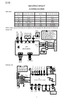
[1] WIRING DIAGRAM

Instruction

Symbol

Symbol Color or Name

Symbol

Symbol Color or Name

WH

White

BN

Brown

YE

Yellow

BU

Blue

RD

Red

BK

Black

YEGN

Yellow/Green

OG

Orange 

VT

Violet

CAP

Jumper cap

GN

Green

COMP

Compressor 

NOTE: Jumper cap is used to determine fan speed and the swing angle of horizontal lover for this model.

Indoor Unit

Please don't touch any 

electronic component or 

terminal when the machine 

is running,stopping or 

has been powered off for 

less than 3 minutes to 

prevent electric shock !

Outdoor Unit

Please don't touch any 

electronic component or 

terminal when the machine is 

running , stopping or has 

been powered off for less 

than 30 minutes to prevent 

the risk of electric shock !

NOTE:

Motor ground only

applies to the

iron shell motor.

Summary of Contents for AE-X36RU

Page 1: ...hould be restored to its original condition and only parts identical to those specified should be used This document has been published to be used for after sales service only The contents are subject to change without notice CONTENTS 2 Troubleshooting for Main Malfunction 14 3 Troubleshooting for Normal Malfunction 29 REFRIGERATION CYCLE 31 1 Refrigerant System Diagram 31 2 PERFORMANCE CURVES 31 ...

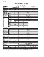
Page 2: ...4 Soft 38 Fan system Drive Direct drive Air flow quantity at cooling Turbo CFM m3 min 736 20 8 2589 73 3 High 647 18 3 Low 530 15 Soft 412 11 7 Air flow quantity at heating Turbo CFM m3 min 736 20 8 2589 73 3 High 647 18 3 Low 530 15 Soft 412 11 7 Fan Cross flow fan Propeller fan Connections Refrigerant coupling Flare type Refrigerant tube size Gas line inch mm 5 8 16 Refrigerant tube size Liquid ...

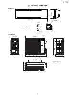
Page 3: ...L DIMENSION Indoor Unit 12 8 326 10 0 253 3 64 92 5 2 2 56 3 64 92 5 6 7 170 53 1 1350 Unit inch mm Thickness 0 9 22 5 Thickness 0 93 23 5 Outdoor Unit 14 6 371 36 914 1 24 609 6 15 7 398 8 31 1 790 38 6 980 16 7 424 2 Unit inch mm ...

Page 4: ...fan speed and the swing angle of horizontal lover for this model Indoor Unit Please don t touch any electronic component or terminal when the machine is running stopping or has been powered off for less than 3 minutes to prevent electric shock Outdoor Unit Please don t touch any electronic component or terminal when the machine is running stopping or has been powered off for less than 30 minutes t...

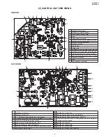
Page 5: ...h frequency terminal OUTDOOR 3 2 1 4 5 6 7 8 9 10 11 12 13 14 15 16 1 Interface of reactor 1 10 Interface of outdoor fan 2 Interface of reactor 2 11 Electric heater band of chassis HEAT2 L 3 U V W three phase interface of compressor 12 Electric heater band of compressor HEAT1 L 4 Overload protection terminal of compressor OVC COMP 13 Interface of neutral wire for compressor electric heating and ch...

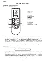
Page 6: ...he same time Under ON status the display will show the corresponding set function icons 1 ON OFF button Press this button can turn on or turn off the air conditioner After turning on the air conditioner operation indicator on indoor unit s display is ON green indicator and indoor unit will give out a sound 2 MODE button Press this button to select your required operation mode When selecting auto m...

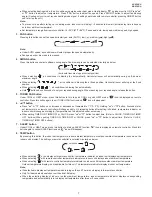
Page 7: ...FAN function and icon will disappear 6 button Press or button once increase or decrease set temperature 1 C 1 2 F Holding or button 2seconds later set temperature on remote controller will change quickly On releasing button after setting is finished temperature indicator on indoor unit will change accordingly Temperature can t be adjusted under auto mode When setting TIMER ON TIMER OFF or CLOCK pre...

Page 8: ...blinking icon resumes displaying Cancel TIMER OFF Under the condition that TIMER OFF is started up press TIMER OFF button to cancel it Note Under on and off status you can set TIMER OFF or TIMER ON simultaneously Before setting TIMER ON or TIMER OFF please adjust the clock time After starting up TIMER ON or TIMER OFF set the constant circulating valid After that air conditioner will be turned on o...

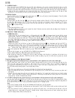
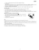
Page 9: ...NG button to select fan blowing angle Replacement of batteries in remote controller 1 Press the back side of remote controller marked with as shown in the fig and then push out the cover of battery box along the arrow direction 2 Replace two 7 AAA 1 5V dry batteries and make sure the position of polar and polar are correct 3 Reinstall the cover of the battery box Battery Cover of battery box Reinst...

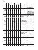
Page 10: ...link 6 times During cooling operation compres sor will stop while indoor fan will operate During heating operation the com plete unit stops Refer to the malfunction analysis overload high temperature resis tant 8 EEPROM mal function EE OFF 3S and blink 15 times OFF 1S and blink 11 times During cooling and drying opera tion compressor will stop while indoor fan will operate During heating operation...

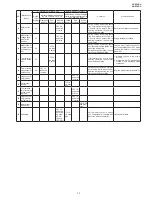
Page 11: ...ed Overload or temperature is too high Malfunction of electric expansion valve EKV 20 Limit decrease frequency due to antifreezing FH OFF 3S and blink 2 times OFF 3S and blink 2 times OFF 1S and blink 4 times All loads operate normally while operation frequency for compres sor is decreased Poor air return in indoor unit or fan speed is too low 21 Voltage for DC bus bar is too high PH OFF 3S and bl...

Page 12: ... During cooling and drying opera tion compressor will stop while indoor fan will operate During heating operation the complete unit will stop operation Refer to the malfunction analysis overload high temperature resis tant 35 IPM protection H5 OFF 3S and blink 5 times OFF 1S and blink 4 times During cooling and drying opera tion compressor will stop while indoor fan will operate During heating ope...

Page 13: ...door fan will operate During heating operating the com plete unit will stop operation There s circuit malfunction on out door units control panel AP1 please replace the outdoor units control panel AP1 47 The four way valve is abnor mal U7 OFF 3S and blink 20 times If this malfunction occurs during heating operation the complete unit will stop operation 1 Supply voltage is lower than AC175V 2 Wirin...

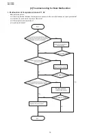
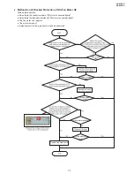
Page 14: ... points Is the wiring terminal between the temperature sensor and the controller loosened or poorly contacted Is there short circuit due to trip over of the parts Is the temperature sensor broken Is main board broken Is the problem fixed Is the problem fixed Is the problem fixed Replace it with the temperature sensor ...

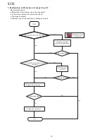
Page 15: ...al of PG motor connected tightly SmoothlyIs the feedback interface of PG motor connected tightly The fan motor can t operate The motor is broken Detectioncircuit of the main board is defined abnormal Is the problem fixed Is the problem fixed Is the problem fixed Is the motor started up Replace the main board Is the problem fixed ...

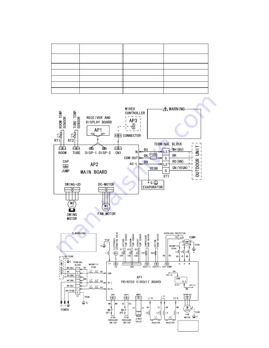
Page 16: ...nts Malfunction Is there jumper cap on the mainboard Is the jumper cap inserted correctly and tightly The jumper is broken Detection circuit of the mainboard is defined abnormal Is the problem fixed Is the problem fixed Is the problem fixed Replace the main board Replace the jumper cap ...

Page 17: ...AY X36RU AE X36RU 17 4 Malfunction of Zero crossing Inspection Circuit Malfunction of the IDU Fan Motor U8 The zero cross detection circuit of the main board is defined abnormal Replace the main board ...

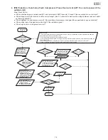
Page 18: ...oltage testing circuit on control panel AP1 Replace the control panel AP1 Measure the AC voltage between terminalL andN on wiring board XT power supply Voltage within 210VAC 250VAC Shut down the power and repair the power supply to restore the range 210VAC 250VAC power on and restart the unit Shut down the power and wait 20 minutes or use DC voltmeter to measure the voltage on the two ends of capa...

Page 19: ...the system pressure is too high and exceeds the permissible range 4 If the charge volume of refrigerant is too much resulting in that the system pressure is too high 5 Other conditions resulting in that the system pressure becomes too high Take corrective actions according to Technical Service Manual and then energize and start the unit If there is any abnormality described above Replace the contr...

Page 20: ...ambient temperature higher than 53 20 minutes after the complete unit is powered off Is heat dissipation of the indoor unit and outdoor unit abnormal Normal protection please operate it after the outdoor ambient temp erature is normalized Improve the heat dissipation environ ment of the unit Does the outdoor fan work normally 1 Check if the fan terminal OFAN is connected correctly 2 Measure the el...

Page 21: ...e for compressor stopping enough Y N Y N N Y Y N Power on the unit Is stop time of the compressor longer than 3 minutes Restart it up after 3 minutes Does startup fail Are the wires for the compressor connected correctly Is connection sequence right Connect the wires as per the connection diagram Replace the control panel AP1 Replace the compressor End Is the problem fixed ...

Page 22: ...tion sequence right Is the connection made in clockwise direction Connect the wires correctly Replace the control panel AP1 Replace the compressor End Out of step occurs in operation Is the outdoor fan working normally Is the outdoor unit blocked by any objects Replace the control panel AP1 Replace the compressor End Remove objects Replace the outdoor fan N Y Y Y Y Y Y Y N N N N N N Measure the el...

Page 23: ...the complete unit is powered off Is the terminal FA for the electronic expansion valve connected correctly Connect the N N N Y Y Y wires correctly Resistances between the first four pins close to the terminal hole and the fifth pin are almost the same less than 100 ohm Replace the electronic expansion valve Replace the control panel AP1 Coolant leakage refilling the coolant End Is the problem fixe...

Page 24: ...of the reactor L of the outdoor unit and the PFC capacitor Whether there is any damage or short circuit Replace it as per the wiring diagram and reconnect the wires Disconnect the terminals for the reactor and measure the resistance between the two terminals of the reactor by an ohm gauge Whether there is any damage or short circuit Replace the reactor Restart the unit Replace the control panel AP...

Page 25: ...rmally before the failure occurs The AP1 voltage detection circuit is at fault Check wiring inside of the indoor and outdoor units Are wires broken Check the communication circuit of the outdoor unit The communication circuit is abnormal Replace the main board of the indoor unit End Replace the main board AP1 of the outdoor unit Is the connection right Check the wiring of the indoor and outdoor un...

Page 26: ...quipment operate normally before the failure occurs The AP1 voltage detection circuit is at fault Check wiring inside of the indoor and outdoor units Are wires broken Check the communication circuit of the outdoor unit The communication circuit is abnormal Replace the main board of the indoor unit End Replace the main board AP1 of the outdoor unit Is the connection right Check the wiring of the in...

Page 27: ...er is fully open Check if the capacity output of outdoor unit is equal to the capacity demand of indoor units Check if the indoor outdoor filters or radiating fins are dirty or blocked Clean the fins The system pipe is blocked Refer to the dial up of indoor and outdoor unit Measure the swing motor and signal input Measure the fan motor and signal input Remove the obstructions Cover up the front pa...

Page 28: ...ompressor running abnormally Is there abnormal sound or oil leakage is the temperature of the shell too high etc Is the indoor outdoor heat exchanger too dirty or are the air inlet and outlet blocked Normal fluctuation is within 10 of the rated voltage on the nameplate no yes no yes no yes no no no yes no yes no yes yes yes yes yes yes yes Troubleshooting for E5 malfunction Adjust the supply volta...

Page 29: ...indoor unit and outdoor unit is improper Check whether the installation position is proper according to installation requirement for air condi tioner Adjust the installation position and install the rainproof and sun proof for outdoor unit Refrigerant is leaking Discharged air temperature during cooling is higher than normal discharged wind temperature Dis charged air temperature during heating is...

Page 30: ...r Cylinder of compressor is blocked Compressor can t operate Repair or replace compressor 6 Air Conditioner is Leaking Possible causes Discriminating method air conditioner status Troubleshooting Drain pipe is blocked Water leaking from indoor unit Eliminate the foreign objects inside the drain pipe Drain pipe is broken Water leaking from drain pipe Replace drain pipe Wrapping is not tight Water l...

Page 31: ...r Accumlator Compressor Connection pipe specification Liquid pipe 1 4 inch 6 35mm Gas pipe 5 8 inch 16mm 2 PERFORMANCE CURVES 1 Operation Characteristic Curve Cooling Heating 0 2 4 6 8 10 12 14 0 20 40 60 80 100 120 0 2 4 6 8 10 12 14 0 20 40 60 80 100 120 Condition Indoor DB 80 6 F WB66 2 F Indoor air flow Super High Pipe length 24 6ft Condition Indoor DB 70 F Indoor air flow Super High Pipe leng...

Page 32: ...r and outdoor unit Inlet and outlet pipe temper ature of heat exchanger Fan speed of indoor unit Fan speed of outdoor unit Compressor revolution rps Indoor Outdoor P MPa T1 F T2 F 80 66 9 95 0 9 1 0 46 8 to 52 8 127 to 96 8 Supper High High 67 Heating Rated cooling condition F DB WB Pressure of gas pipe connect ing indoor and outdoor unit Inlet and outlet pipe temper ature of heat exchanger Fan sp...

Page 33: ... UNIT 1 Before disassembly of the unit Axonometric drawing for the completeunit 2 Remove the filters 1 Open the panel panel 2 Remove the two 2 filters filter 3 Remove the display Remove the two 2 screws fixing display and then remove the display with lead wire Display Lead wire 4 Remove the panel Pull the hooks at both sides slightly and then remove the panel Hook Panel 5 Remove the horizontal lou...

Page 34: ... on the right side of the electric box Hook 3 Remove the electric box cover Electric box cover 10 Remove the temperature sensor and the earth wire 1 Pull out the indoor temperature sensor 2 Remove the earth screw and then remove the earth wire Temperature sensor Earth screw 11 Remove the electric box 1 Pull out the six 6 connectors on PCB board 2 Remove the two 2 screws on the electric box Screw E...

Page 35: ... the evaporator 1 Remove the six 6 screws between evaporator and bottom case Screws 2 Turn over the indoor unit and adjust the pipe line to the position as shown by the broken line 3 Lift up the evaporator and then remove the evaporator Evaporator 17 Remove the fixing plate of motor Remove the two 2 screws on the fixing plate of motor and then remove the fixing plate of motor Screw 18 Remove the c...

Page 36: ...the terminal cover 2 Remove the two 2 screws fixing the pipe cover 3 Remove the three 3 screws fixing the Front Side Plate 4 Remove the eight 8 screws fixing the top plate 5 Remove the seven 7 screws fixing the front panel 6 Remove the eleven 11 screws fixing the right side panel ...

Page 37: ...tors 9 1 Disconnect the seven 7 connectors 9 2 Disconnect the four 4 connectors 9 3 Disconnect the six 6 connectors 9 4 Disconnect the three 3 connectors after removing the lock part 10 Remove the nine 9 screws fixing the PWB 11 Loosen the three 3 fixing bands fixing the lead wire 12 Cut the fixing band and unscrew the two 2 screws ...

Page 38: ...crews fixing the reactor 16 Remove the one 1 screw fixing the reactor box cover 17 Disconnect the two 2 connectors and remove the four 4 screws fixing the reactor 18 Remove the four 4 screws fixing the reactor box 19 Cut the four 4 fixing bands 20 Remove the topside compressor cover 21 Remove the compressor cover 22 Remove the nut fixing the terminal cover Compressor cover Compressor cover ...

Page 39: ...mistor lead wire 24 Unhook the hook of the spring fixing the compressor heater assembly 25 Remove the damper rubber 26 Turn the coil and remove it 27 Remove the nut fixing the propeller fan 28 Loosen the fixing band fixing the lead wire 29 Cut the three 3 fixing bands 30 Cut the insulator Cut Damper rubber ...

Page 40: ... 2 screws fixing the motor angle 32 Remove the four 4 screws fixing the fan motor 33 Remove the three 3 screws fixing the heater cover 34 Remove the sixteen 16 screws fixing the heater assembly Position of the thermistors White Yellow Black ...

Page 41: ...ublished to be used for after sales service only The contents are subject to change without notice AYX36RU HOW TO ORDER REPLACEMENT PARTS To have your order filled promptly and correctly please furnish the following information 1 MODEL NUMBER 2 REF NO 3 PART NO 4 DESCRIPTION MODELS INDOOR UNIT AY X36RU SPLIT TYPE ROOM AIR CONDITIONER OUTDOOR UNIT AE X36RU PartsGuide 1 INDOOR UNIT 2 OUTDOOR UNIT IN...

Page 42: ...6RU 2 1 INDOOR UNIT 60 40 36 49 50 59 55 39 38 54 41 53 52 31 1 2 3 4 5 7 7 48 7 6 32 33 34 12 19 15 23 27 22 14 13 13 13 28 29 13 21 44 20 42 58 57 47 46 45 61 43 26 30 18 17 16 24 25 35 37 51 56 11 10 9 8 ...

Page 43: ...r Plate 29 9JX26112325 AC Motor Fixed Clip 2 30 9JX26112324 AF Motor Fixed Clip 1 31 9JX1521210701 AR SteppingMotor 32 9JX26112070 AC Press Plate Crank 33 9JX10582041 AC Crank Guide 34 9JX10562004 AC Upper Crank 35 9JX10562005 AC Lower Crank 36 9JX10000201845 BR Electric Box Assy 37 9JX201022502 AV Electric Box 38 9JX4201026902 AR Terminal Board 39 9JX30138000192 BM Main Board 40 9JX30565124 AX Di...

Page 44: ...AYX36RU 4 2 OUTDOOR UNIT 45 14 44 15 16 22 10 38 37 39 35 12 42 42 26 6 4 3 1 40 2 7 5 9 8 11 46 25 24 31 30 29 27 28 21 17 34 18 19 33 22 20 23 32 43 13 ...

Page 45: ...X01175037 AL Condenser Support Plate 20 9JX01802876 BG Motor Support Sub Assy 21 9JX01255007 BC Top Cover Sub Assy 22 9JX43130192 BE Reactor 23 9JX76614102 AD Pass Wire Ring Sub assy 24 9JX26235401 AD Left Handle 25 9JX01305043P AY Left Side Plate 26 9JX1570280205 CF Fan Motor 27 9JX10000100338 CK Electric Box Assy 28 9JX30148360 CH Main Board 29 9JX01425281 AQ Electric Box Cover 30 9JX01413174 AV...

Page 46: ...0701 1 31 AR 9JX1570280205 2 26 CF 9JX20012712 L2 1 1 BE 9JX20022159 1 4 BD 9JX201022502 1 37 AV 9JX201022523 1 54 AF 9JX2011204404S 1 41 AL 9JX20122124 1 28 AF 9JX20182138 1 12 AY 9JX22202928 1 15 BR 9JX22245003 2 14 AL 9JX24212041 1 20 AH 9JX2421204201 1 25 AG 9JX24212120 1 2 AC 9JX242520053 1 13 AC 9JX26112070 1 32 AC 9JX26112071 1 26 AF 9JX26112158 1 11 AC 9JX26112324 1 30 AF 9JX26112325 1 29 ...

Reviews: